
User's Manual
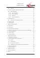
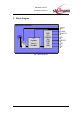
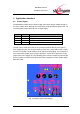
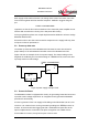
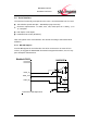
Table Of Contents
- Introduction
- Block Diagram
- Application Interface
- Pin Description
- Electrical Characteristics
- Mechanical Characteristics
- Approvals/Certifications
- Related Documents
- Ordering Information
- History

BlueMod+C11/G2
Hardware Reference
www.stollmann.de Page 8 of 42
3 Application Interface
3.1 Power Supply
The BlueMod+C11/G2 has two power supply rails, which always should be kept on
the same voltage level. Although we recommend using two different power rails, it is
as well possible to feed both rail from a single supply.
Pin #
Signal
Usage
C-13
3V3
Supply for digital and low power RF circuitry,
C-16
3V3-PA
Supply for RF Amplifier
C-14
GND
Reference Supply
C-15
GND
Reference Supply
The pin order is made such that on the customer hardware directly at the pins of
each supply pair pins (C-13/C14) and pins (C-16/C-15) a 10uF X5R ceramic capaci-
tor with for example a 1206 footprint can be placed for decoupling. It is recommend-
ed to add further smaller value ceramic capacitors. These values depend on noise
frequencies on the supply rail. The following picture shows a sample layout with two
linear regulators in SOT23-5 housings and various capacitors in SMT shapes 0402,
0805 and 1206.
Fig. 2 Sample Layout Power Supply