
User's Manual
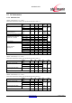
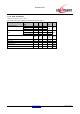

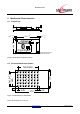


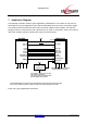
Table Of Contents
- 1 Introduction
- 2 Block Diagram
- 3 Application Interface
- 4 Module Pins
- 5 Electrical Characteristics
- 6 Mechanical Characteristics
- 7 Application Diagram
- 8 Approvals/Certifications
- 9 Related Documents
- 10 Packing
- 11 Ordering Information
- 12 History

BlueMod+S/AI
www.stollmann.de Page 39 of 52
7 Application Diagram
The following schematic shows a typical application of BlueMod+S. The module is connected to
some MCU running the application layer. MCU and BlueMod+S use the same 3,3V power supply.
The serial interface has RTS/CTS flow control and UICP support in this example. The optional
hangup feature to close down the link is provided. As an option to save power, there is an external
slow clock oscillator. All other module pins may be left unconnected.
Host MCU
VDD
GND
+3V3
GPIO (o)
In this example BlueMod+S is connected to an MCU supporting UICP, RTS/CTS flow control and Hangup.
The slow clock oscillator (32,768kHz ) is optional; it helps to save power during power down states.
1k
BlueMod+S/AI
E-6,F-6
VSUP
B-1
EXT-RES#
UART-RXD
UART-TXD
UART-CTS#
UART-RTS#
GPIO[4]/Hangup
TXD (o)
RXD (i)
RTS# (o)
CTS# (i)
GPIO (o)
XL-IN/SLCK
32,768kHz square
or clipped sine
+3V3
The oscillator is optional. Leave A-6 open
if the oscillator is not present.
You can also connect an 32,768kHz XTAL
and two capacitors at A-6 and A-5.
B-4
D-4
A-6
all GND pads (14) must be connected.
Blocking capacitors not shown.
pushpull or OD
pushpull
A-5
XL-OUT
D-2
F-4
F-3
D-7
IUR-IN#
D-5
IUR-OUT#
GPIO/DSR# (o)
GPIO/DTR# (i)
Figure 18: Typical Application Schematics