
User's Manual
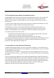


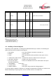


Table Of Contents
- 1 Introduction
- 2 Block Diagram
- 3 Application Interface
- 3.1 Power Supply
- 3.2 Power-up / -down Slew-Rate
- 3.3 Reset
- 3.4 Supply Voltage Monitor
- 3.5 Serial Interface
- 3.6 GPIO Interface
- 3.7 I2C Interface0F
- 3.8 SPI Serial Peripheral Interface1F
- 1.1
- 3.9 Bluetooth Radio Interface
- 3.10 WLAN Coexistence Interface2F
- 3.11 Slow Clock Interface
- 3.12 Test Mode Enable
- 3.13 Pin Strapped System Memory Boot Mode Invocation
- 3.14 Operating in a Power-Switched Environment
- 3.15 Serial Wire Interface
- 4 Module Pins
- 5 Electrical Characteristics
- 6 Mechanical Characteristics
- 1
- 7 Application Diagram
- 8 Approvals/Certifications
- 9 Related Documents
- 10 Packing
- 11 Ordering Information

BlueMod+SR/AI
BlueMod+SR/AP
Hardware Reference
Release r04d01 www.stollmann.de Page 25 of 65
E-1 BOOT0
r
I-PD
(2)
system memory bootloader
E-3 DNU
(4)
reserved leave open (serial wire)
D-6 DNU
(4)
r
leave open (serial wire)
C-2 DNU
(4)
reserved leave open
B-3 DNU
(4)
reserved leave open
A-5 DNU
(4)
reserved
leave open
F-5 DNU
(4)
reserved leave open
E-5 DNU
(4)
reserved leave open
Table 5: Application Specific Pin Assignments, SPP
Notes:
(1)
a discrete pull-up resistor is used
(2)
a discrete pull-down resistor is used
(3)
function depends on firmware
(4)
DNU: Do Not Use, Do Not Connect
4.3 Handling of Unused Signals
Depending on the application, not all signals of BlueMod+SR may be needed. The following list
gives some hints how to handle unused signals.
• EXT-RES# If no external Reset is needed: Leave open (*)
• BOOT0 (*) [leave open]
• SLCK If no external slow clock is provided: Leave open or tie to
GND
• UART-RTS#, UART-CTS# If neither flow control nor UICP is used: Leave open
• IUR-OUT#, IUR-IN# If UICP is not used: leave open
• BT-ACT, BT-STAT, If there is no WLAN device on the same PCB: Leave open
BT-PER, WLAN-DNY
• TESTMODE# Leave open
• unused GPIOs Leave open
• SWDIO, SWCLK Leave open. Only needed for debug purposes.
(*) for being able to update the firmware, it is strongly recommended to provide for a means to set
BOOT0 temporarily to logic high level, and to reset the module; see chapter 3.13.