
User's Manual


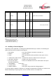


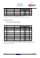
Table Of Contents
- 1 Introduction
- 2 Block Diagram
- 3 Application Interface
- 3.1 Power Supply
- 3.2 Power-up / -down Slew-Rate
- 3.3 Reset
- 3.4 Supply Voltage Monitor
- 3.5 Serial Interface
- 3.6 GPIO Interface
- 3.7 I2C Interface0F
- 3.8 SPI Serial Peripheral Interface1F
- 1.1
- 3.9 Bluetooth Radio Interface
- 3.10 WLAN Coexistence Interface2F
- 3.11 Slow Clock Interface
- 3.12 Test Mode Enable
- 3.13 Pin Strapped System Memory Boot Mode Invocation
- 3.14 Operating in a Power-Switched Environment
- 3.15 Serial Wire Interface
- 4 Module Pins
- 5 Electrical Characteristics
- 6 Mechanical Characteristics
- 1
- 7 Application Diagram
- 8 Approvals/Certifications
- 9 Related Documents
- 10 Packing
- 11 Ordering Information

BlueMod+SR/AI
BlueMod+SR/AP
Hardware Reference
Release r04d01 www.stollmann.de Page 28 of 65
5.4 Environmental Requirements
Item Symbol Absolute Maximum Ratings Unit
Storage temperature range T
stg
-40 to +85 °C
Operating temperature range T
op
-30 to +85 °C
Table 9: Environmental Requirements
5.5 Digital I/O Including EXT-RES#
STM32 MCU and CSR8811 do have different electrical I/O characteristics.
All Module I/O pins are connected directly to these chips without signal conditioning except for
some pull-up/pull-down resistors (as indicated). Therefore the electrical characteristics are split in
different tables.
STM-Related Signals:
• EXT-RES# (additional filter-C 100n to GND)
• UART-TXD, UART-RXD, UART-CTS#
• UART-RTS# (pull-up resistor 470kΩ)
• IUR-IN#
• IUR-OUT# (pull-up resistor 470kΩ)
• GPIO[0..8], TESTMODE#
• BOOT0 (pull-down resistor 100kΩ)