
User's Manual
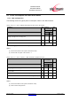
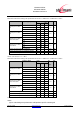


Table Of Contents
- 1 Introduction
- 2 Block Diagram
- 3 Application Interface
- 3.1 Power Supply
- 3.2 Power-up / -down Slew-Rate
- 3.3 Reset
- 3.4 Supply Voltage Monitor
- 3.5 Serial Interface
- 3.6 GPIO Interface
- 3.7 I2C Interface0F
- 3.8 SPI Serial Peripheral Interface1F
- 1.1
- 3.9 Bluetooth Radio Interface
- 3.10 WLAN Coexistence Interface2F
- 3.11 Slow Clock Interface
- 3.12 Test Mode Enable
- 3.13 Pin Strapped System Memory Boot Mode Invocation
- 3.14 Operating in a Power-Switched Environment
- 3.15 Serial Wire Interface
- 4 Module Pins
- 5 Electrical Characteristics
- 6 Mechanical Characteristics
- 1
- 7 Application Diagram
- 8 Approvals/Certifications
- 9 Related Documents
- 10 Packing
- 11 Ordering Information

BlueMod+SR/AI
BlueMod+SR/AP
Hardware Reference
Release r04d01 www.stollmann.de Page 32 of 65
The following table shows the average power consumption of BlueMod+SR in LE-mode operating
in the peripheral device role.
VSUP = 3,3V, T
amb
= 25°C, Tx power = +7 dBm, all GPIOs and UART lines open
Condition Note Current
Consumption
Unit
Slow clock
Extern
Intern
I
Avg
I
Avg
Idle, Advertising on 3 channels, advertising interval: 1,28s
3,5 3,7 mA
Idle, Advertising on 3 channels, advertising interval: 1,28s, UICP
active serial Interface down
0,31 0,46 mA
Connected, connection interval: 40ms, no data traffic
(2,3)
4,8 5,0 mA
Connected, connection interval: 37,5ms, no data traffic
(2,4)
5,3 5,4 mA
Connected, connection interval: 37,5ms
data traffic
(2,4)
Tbd Tbd mA
Table 15: Supply Current BLE Peripheral Device Role
Notes:
(2)
connection parameters are setup by the central device when connection is established
(3)
no data to be transmitted, central device sends an empty packet (80 bit) then peripheral device answers (empty
packet: 80 bit)
(4)
these are a typical connection parameters used by an iPhone, iPad or iPad mini device in the central device role