
User's Manual
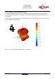
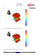

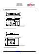


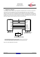
Table Of Contents
- 1 Introduction
- 2 Block Diagram
- 3 Application Interface
- 3.1 Power Supply
- 3.2 Power-up / -down Slew-Rate
- 3.3 Reset
- 3.4 Supply Voltage Monitor
- 3.5 Serial Interface
- 3.6 GPIO Interface
- 3.7 I2C Interface0F
- 3.8 SPI Serial Peripheral Interface1F
- 1.1
- 3.9 Bluetooth Radio Interface
- 3.10 WLAN Coexistence Interface2F
- 3.11 Slow Clock Interface
- 3.12 Test Mode Enable
- 3.13 Pin Strapped System Memory Boot Mode Invocation
- 3.14 Operating in a Power-Switched Environment
- 3.15 Serial Wire Interface
- 4 Module Pins
- 5 Electrical Characteristics
- 6 Mechanical Characteristics
- 1
- 7 Application Diagram
- 8 Approvals/Certifications
- 9 Related Documents
- 10 Packing
- 11 Ordering Information

BlueMod+SR/AI
BlueMod+SR/AP
Hardware Reference
Release r04d01 www.stollmann.de Page 48 of 65
6.4 Placement Recommendation
To achieve best radio performance for BlueMod+SR/AI, it is recommended to use the placement
shown in Figure 18.
max.0,5
4,5
10
10
max.0,5
10
15
no bare copper (exept solder pads for module)
no copper and components on any layer
no components on any layer
provide solid ground plane(s) as large as possible around
17
no conductive parts allowed
20
20
40
area
Figure 18: BlueMod+SR/AI Placement Recommendation
6.5 Housing Guidelines
The individual case must be checked to decide whether a specific housing is suitable for the use of
the internal antenna. A plastic housing must at least fulfill the following requirements:
• Non-conductive material, non-RF-blocking plastics
• No metallic coating
• ABS is suggested
6.6 Antenna Issues
BlueMod+SR is shipped with 2 different antenna designs:
• BlueMod+SR/AI comprises a ceramic antenna which as a component is soldered to the
circuit board. This is functional for a BlueMod+SR/AI integrated into a plastic housing. No
additional antenna is required.
For an external antenna to be set in, e.g. because the BlueMod+SR is integrated into a metal
housing, the ceramic antenna is replaced.
• BlueMod+SR/AP routes the antenna signal to pin A-8
The gain of the external antenna shall not exceed +2dBi.
When using an external Antenna the antenna is fixed and cannot be removed or replaced by the
end user. The performance of the internal antenna respectively the external antenna has in any