
User's Manual


EcoWave
Installation
Guide
Telkonet,
Inc.
Wiring the EcoInsight/EcoSource
10200 W. Innovation Dr., Ste. 300
Revision 9
Milwaukee
, WI 53226
Page
4
(800) 380
-
9640
www.telkonet.com
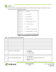
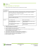
16. Refer to either the wiring diagram provided by your Telkonet Project Manager for this install or use the
wiring pinouts below in Figure 1and Table 1.
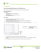
Figure 1: EcoInsight/EcoSource Wiring Pinout
Table 1: EcoInsight/EcoSource Wiring Pinout
Pin
Label on Backplate
Function
1
R (Power)
12
-
277VAC power from HVAC, used to power the thermostat
2
C (Common)
AC Common
3
AUX (Auxiliary)
User defined
4
W1 (Heat) (Strip)
Heat call
or strip heat call (depends on programming)
5
Switched Power 1 (W1/Y1)
Provides alternate power for W1 and Y1
6
Y1 (Cool) (Comp)
Cool/Compressor call
7
G (Fan)
Fan Call
-
Low speed
8 O (B) (G2) (Y2) (Changeover)
Multi
-
use
-
depends on programming and
site requirements:
• Changeover
• 2
nd
Stage Fan
• 2
nd
Stage Cooling
9
Switched Power 2
(G/O/W2)
Provides alternate power for G, O, and W2
10 W2 (Y2) (G2) (G3) (Multi-speed)
Multi
-
use
-
depends on programming and site requirements:
• 2
nd
stage heat
• Electric heat (for HPs with strip heat, etc.)
• Emergency heat
• Other