
Installation Manual

Titel Reg. Nr. Date Author Revision
Installation Manual MCG TQ377 TQ-18-496 2019-05-29 Erik Ljung p1k
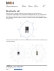
Electrical installation
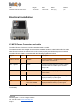
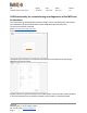
X1 X2 X3
X1 MCG Power Connector and cable
The MCG Power Connector is an M12 standard male A-coded.
The attached cable is a straight connector M12 standard female A-coded cable with free ends.
Note! Some functions are critical for the unit to work properly and shall always be connected.
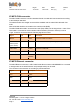
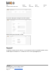
The MCG Power Cable is connected with the following signals and colors:
Signal
PIN
Color
Description
UIN 10-36 VDC
1
BROWN
Connect to battery + (positive) before main
power switch via a 3A fuse
IO1 – Ignition
2
WHITE
Connect to ignition signal on machine. Ignition
must be turned on to wake up the unit from
sleep mode
A GND
3
BLUE
Connected to battery – (negative) before main
power switch
IO2
4
BLACK
Connect IO2 signal Digital signal or analogue
signal (0-30VDC) or pulse signal
IO3
5
GRAY or
YELLOW/ GREEN
Connect IO3 signal Digital signal or analogue
signal (0-30VDC/0-5VDC) or pulse signal
Note! At least the three wires in MCG X1 pin 1-3 Power cable needs to be connected for full
functionality.
TelliQ AB
Glasbruksgatan 1, 732 31 Arboga, Sweden
Tel: +46 589 12370, www.oem.telliq.com
Page:6