Wireless LAN Access Point User’ s Manual Version 1.
Copyright © 2003 by manufacturer. All rights reserved. No part of this documentation may be reproduced in any form or by any means or used to make any derivative work (such as translation, transformation, or adaptation) without written permission from the copyright owner. All the other trademarks and registered trademarks are the property of their respective owners.
FCC Radiation Exposure Statement This device and its antennas must operate with a separation distance of at least 20 cm from all persons and must not be co-located or operating in conjunction with any other antenna or transmitter. End users must be provided with specific operating instructions for satisfying RF exposure compliance. This product has been certified in France, Germany, Italy, Spain, Sweden, UK, and US.
MPE Statement (Safety Information) Your device contains a low power transmitter. When device is transmitted it sends out Radio Frequency (RF) signal. LIMITED WARRANTY This product is warranted by manufacturer to be free from defects in material and workmanship for one (1) year from the date of purchase unless otherwise stated.
Table of Contents 1. INTRODUCTION........................................................................................... 5 1.1 Features .................................................................................................... 5 1.2 Applications ............................................................................................. 5 2. INSTALLATION............................................................................................ 7 2.1 Product Kit ..............................
1. INTRODUCTION Wireless LAN is local area networking without wires, which uses radio frequencies to transmit and receive data between PCs or other network devices. Wireless LAN is able to configure independent networks and infrastructure networks. The former is suitable for small or temporary peer-to-peer configurations, and the latter is offering fully distributed data connectivity via micro cells and roaming.
at customer sites. Trade shows, exhibitions, retailers, airline, and shipping companies need additional workstations for the peak periods of data traffic.
2. INSTALLATION Please follow steps described in Section 2.1 through 2.8 to install your AP -- including hardware, driver, and utilities. 2.1 Product Kit Before starting installation, please make sure the Wireless Access Point (AP) package you purchased includes the following four items: 1) Wireless Access Point with one antenna. 2) CD-ROM (containing Driver/Utility, and User’ s Manual). 3) User’ s Manual (hard copy). 4) Power adapter with power cord.
LED LAN Off No power. No network connection. Nil. RSS No power. Table 1. LED Indicators On Flash Link to hub, but no LAN traffic is detected. The network traffic. heavier the traffic, the faster the LED flashes. Nil. RSS is detected. The bigger the RSS, the faster the LED flashes. Power on Nil. Power Nil. Nil. Radio traffic is detected. The heavier the traffic, the faster the LED flashes. WLAN 2.
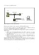
2.6 Connect to an ADSL modem PSTN ADSL splitter Phone line Phone line Phone Ethernet Cable Notebook with Wireless LAN Card, Wireless USB Dongle ADSL MODEM (ATU-R) Direct Connection of AP to ADSL Modem Please note the conditions for the connection of AP with ADSL modem: If the AP is directly connected to the ADSL modem output, an Ethernet cable type (crossover or straight-through) is dependent on ADSL modem.
2.7 Install Utilities Before installing the utilities into your PC, you have to ensure that your PC is running under Windows 98, Me, NT, 2000, or XP operating system and has minimum 5 Mbytes free disk space. Please follow the steps below to install three utilities, AP Utility, SNMP Manager and RSSTool. The first is used for the local configuration, the second is the remote configuration, and the last is the RSS test tool.
3) Follow the prompted instructions to finish the installation. 4) Restart your PC when prompted. 2.8 Install AP’ s Driver You may skip the AP’ s driver installation on the conditions that: 1) Your PC cannot connect to AP through an USB cable. 2) Your PC is running Windows 95 or NT where USB connection is not supported. 3) The local configuration is needed. Please follow the steps below to install the AP’ s driver.
3) Put the supplied CD-ROM in the CD-ROM drive. 4) The driver installation procedure will guide you through the standard steps from your operating system.
5) Restart your PC when prompted. 3. CONFIGURATION After you have completed the Installation process of Section 2 successfully, please follow this section to configure the settings of AP in order to fit in your environment. There are three utilities available, AP Utility、 SNMP Manager and RSSTool. The first is used for local configuration, the second is used for remote configuration, and the last is the RSS test tool. They are described in Sections 3.1 、 3.2 and 3.3 respectively.
3.1 AP Utility Before running AP Utility, you have to make sure that: 1) Your PC is connect ed to the AP properly through an USB cable. 2) Your PC is running under Windows 98, Me, 2000, or XP. 3) AP Utility has been installed (refer to Section 2.7). 4) The AP’ s driver has been installed (refer to Section 2.8). 5) The AP is turned on. Run the AP Utility from Start, Program, Access Point Utilities, and AP Utility. A window AP Utility Application will be displayed.
2) Reset AP: Reset the AP and new configuration will take effect. 3) Restore Default: Restore the factory default values (refer to Section 6). After you click the Configuration button, a window AP Configuration with the current settings will be displayed. Click the Get button to receive the settings in configuration window. Click the listed identifier and press the Modify button, a popped-up window allows you to input the new setting.
1) Rescan: Rescan the AP on the same subnetwork. 2) Start: Start send message to remote AP. 3) Abort : Stop send message to remote AP. Note: When RSSTool is running, you can’ t run SNMP Manager at the same time. 3.4 Web Management The built-in Web Management provides you with a set of user-friendly graphical user interfaces (web pages) to manager your Access Points. With the assigned IP address (e.g. http://192.168.1.100/, 192.168.1.
2) A password request page will show, and enter “public”(the default password) in the Password field. Then click the Submit button. Then you can monitor and configure the Access Point. If you have difficulty in using it, please click the Help for the detailed description about how to operate the Web Manager.
4. CONFIGURE AP AS BRID GE - BLEND MODE (POINT TO MULTIPOINT MODE AND POINT TO POINT SETTINGS) 4.1 Block Diagram We assume that there are three LANs and they will be connected to each other via AP by using AP bridge function. For three APs (AP1, AP2 and AP3) in the following diagram, they can be configured to act as bridges via the SNMP Manager or the AP utility. 4.2 Configuration via SNMP manager 4.2.1 Open Access Point SNMP Manager window See the description in section 3.
In the menu bar, click File, a pull-down menu will allow you to select Connect to Access Point or Find Access Point: If you know the AP’ s IP address, then select Connect to Access Point. If you do not know the AP’ s IP address, then select Find Access Point. Wait for few seconds, and select the right AP and click Connect. Then the Connect to Access Point window will be displayed. Enter the password in the Community field, which is already defined via the AP Utility.
4.2.
• Click on • Select Wireless Bridge, and then Point to Multi Point, finally click on OK button to go back to Wireless Operational Settings window. , the following window will be displayed.
Step 2: Assign ESSID and Channel for AP1. • At Wireless Operational Settings window, set values for ESSID and Channel fields. The values for ESSID and Channel should be the same for all three APs (AP1, AP2 and AP3), so they can be formed as a group and connected to the available bridge AP. And then click on OK button to go back to the Access Point SNMP Manager window. Step 3: Assign DHCP server accessing method for AP1.
• • Click DHCP Enable and select Ethernet in Primary Port, then click on OK button to go back to the Access Point SNMP Manager window. The Primary Port is the path for connecting DHCP Server to get IP address. Because AP1 is connected to DHCP Server via Ethernet port, so the setting must be Ethernet. Click File and select Download Changes, so all your changes will be download to the AP1.
• Click on . The Operation Mode window will be displayed. • At Operation Mode window, select Wireless Bridge and Point to Point, and set AP1 MAC address into Remote MAC Address field, then click on OK button to come back to Wireless Operational Settings window. • Set values for ESSID and Channel fields. The values for ESSID and Channel should be the same for AP1, AP2 and AP3, so they can be formed as a group and communicate to each other.
Access Point SNMP Manager window. Step 6: Assign DHCP server accessing method for AP 2 and AP3. • At Access Point SNMP Manager window, click Setup, select Bridge, and then IP Configuration. The following window will be displayed. • Click DHCP Enable and select Wireless in Primary Port, then click on OK button. The Primary Port is the path for connecting DHCP Server to get IP address. However, AP2 and AP3 are connected with DHCP Server via wireless connection, so the setting must be Wireless.
4.2.3 Wireless Repeater Mode This mode is used in order to increase the coverage area of an ESS. The Wireless Repeater starts acting as an AP after it has associated itself with another AP (Parent AP). From that point on, STAs can get associated to it.
• Click on • Select Access Point, finally click on OK button to go back to Wireless Operational Settings window. , the following window will be displayed. Step 2: Assign ESSID and Channel for AP1. • At Wireless Operational Settings window, set values for ESSID and Channel fields. The values for ESSID and Channel should be the same for AP2. And then click on OK button to go back to the Access Point SNMP Manager window.
Step 3: Assign DHCP server accessing method for AP1. • At Access Point SNMP Manager window, click Setup, select Bridge, and then IP Configuration. The following window will be displayed. • • Click DHCP Enable and select Ethernet in Primary Port, then click on OK button to go back to the Access Point SNMP Manager window. The Primary Port is the path for connecting DHCP Server to get IP address. Because AP1 is connected to DHCP Server via Ethernet port, so the setting must be Ethernet.
• • Click DHCP Enable and select Wireless in Primary Port, then click on OK button. The Primary Port is the path for connecting DHCP Server to get IP address. However, AP2 is connected with DHCP Server via wireless connection, so the setting must be Wireless. Click File and select Download Changes to download the change to AP2. Step 6: Assign Repeater mode and remote AP1’ s MAC address to AP2. • At Access Point SNMP Manager window, click Setup, select Wireless LAN, and then Operational Settings.
• Click on • At Operation Mode window, select Wireless Repeater, and set AP1 MAC address into Remote MAC Address field, then click on OK button to come back to Wireless Operational Settings window. , the Operation Mode window will be displayed.
• Set values for ESSID and Channel fields. The values for ESSID and Channel should be the same for AP1. And then click on OK button to go back to Access Point SNMP Manager window. Note: The Repeater can be configured with the SNMPManager through the wireless STAs associated to it or the PCs in the Wired LAN behind the Parent AP. 4.3 Adjust the best angle of antenna Step 1: Open RSSTool window See the description in section 3.3 to open the RSSTool from the LAN1’ s PC or NB.
Step 2: Confirm the remote IP If you know the AP2’ s IP address, then type it in the “Remote IP” blank. If you do not know the AP2’ s IP address, then click Rescan. Wait for few seconds, and select the right AP name from the pull-down menu. Step 3: Click “Start” button When you click the “Start” button, the RSSTool will send message to the AP2. You can adjust the AP2’ s antenna until AP2’ s Led of RSS bright. Step 4: Click “Abort” button If you have adjusted the AP2’ s antenna, you can stop this tool.
5. SPECIFICATIONS General Standards compliance Security Hardware RF Data rate Modulation Coding Number of channels Host interface Transmit power Receive sensitivity Power Range IEEE 802.3 and 802.11b WEP 64-bit, 128-bit, encryption RC4 Frequency range: 2.4 ~ 2.4835GHz 11Mbps / 5.5Mbps / 2Mbps / 1Mbps DSSS (Direct Sequence Spread Spectrum) DBPSK/DQPSK 1, 2Mbps: 11 chip/bit Barker Coding 5.
Dimensions Weight Certificate EMC Relative Humidity 95% (non-condensing) 6.6” x 4.6” x 1.4” (167.0 x 117.5 x 35.5 mm), without antenna 12.3 oz. (350 grams), excluding power adapter U.S.: FCC Part 15, sections 15.247, 15.205, 15.
6. GLOSSARY The following glossary is for your reference, and is not directly related to the installation of your Access Point. - Wireless Access Point (AP) – Any entity that has station functionality provides access to the distribution services via the wireless medium (WM) for associated stations. - Ad-Hoc – A network is composed solely of stations within mutual communication range of each other via the wireless medium (WM). An ad hoc network is typically created in a spontaneous manner.
- RTS/CTS Threshold – Should remain at its default setting of 2,346. A preamble is a signal used to synchronize the transmission timing between two or more systems. A series of transmission pulses is sent before the data to indicate that “someone is about transmit data.” This ensures that systems receiving the information correctly when the data transmission starts. - - Shared Key – Is when both the sender and recipient share a secret key.
7. DEFAULT SETTINGS No. Identifier 1 Eth_IP_Address 2 Eth_SubMask 3 ESSID 4 Auto Rate Fall Back 5 Channel 6 Fragmentation Threshold 7 RTS Threshold 8 WEP Type 9 WEP Key 10 Key64 1 Description Default Value Possible Values AP’ s IP address 192.168.1.100 Subnet mask 255.255.255.0 Extended service set ID WLAN-AP Transmission rate is Enable “Enable”, “Disable”. subject to the past transmission status. Designate operating 1 for FCC, IC, FCC/IC: 1 to 11, radio channel ETSI, MKK.
No. Identifier Description Default Value Possible Values 15 Key128 2 128-bit WEP value of key 2 “00” to “FF” for each field. 16 Key128 3 128-bit WEP value of key 3 17 Key128 4 128-bit WEP value of key 4 18 Preamble Type The appropriate frame format for transmission to physical layer. “Open System”: the access to AP is valid if the security key of station is not set. “Shared Key”: the access to AP is valid if the security key of station matches with AP’ s.
No. Identifier Description Default Value Possible Values 24 Operational Mode Which operation mode is taken Access Point “WBridge Point to MultiPoint”, “Access Point”, “Access Point Client”, “WBridge Point to Point”, ”Wireless Repeater”.
No. Identifier Description 37 Send Back Broadcast Enable The AP send back to Enable the air roadcast traffic received from the air. The AP forward Enable broadcast traffic to the air. Port will be used for Both Ports the AP configuration. “Enable”, “Disable”. The AP send back to Enable the air unicast traffic received from the air. AP support the Enable International Roaming function “Enable”, “Disable”. 42 802.1x Enable Start the 802.
8. WIRELESS LAN SYSTEM The contents in this section, which are not directly related to the installation of your Access Point, are for you to have better understanding of a Wireless LAN system. 8.1 802.11 Ad-Hoc Configuration An 802.11 Ad-Hoc wireless LAN is a group of computers, each equipped with one wireless LAN card, connected as an independent wireless LAN. Computers in a specific 802.11 Ad-Hoc wireless LAN must be configured at the same radio channel and BSS ID. 802.
Infrastructure configuration is applicable to enterprise scale for wireless access to central database, or wireless application for mobile workers. Two APs can be used as a point-to-point link between two LANs. LAN interconnection is applicable to a wireless backbone between buildings.
Figure 3.
9. DISABLE IP FILTERING Use AP Utility to disable IP Filtering 1) Run AP Utility, then click Configuration. 2) If the item IP Filtering is not Disable, click Modify. 3) Select Disable, then click OK.
4) Click Set. 5) Click Yes, then wait for download completion. 6) Exit AP Utility.
Use SNMP Utility to disable IP Filtering 1) Run SNMP, then press Setup -> Bridge -> Filtering 2) Un-check IP Routing, then click OK. 3) Press File -> Download Change. 4) Exit SNMP Utility.