TPRM ProductSpec.doc TPRM Product Specification V1.14 1998and 1999 by: TeLLUS Technology, Inc.
TPRMTPRM ProductSpec.doc Proprietary Information Tellus Technology, Inc. Table of Contents 1. Introduction ................................................................................................. 1 2. Hardware Interface...................................................................................... 1 3. Software Interface ....................................................................................... 4 4. Operation Procedures .................................................
TPRM ProductSpec.doc 1. Introduction This document describes the specification of a CDPD module, which is designed for system integrators that require a CDPD modem. Section 2 describes the hardware interface for this module. The module has a serial interface connector for the Host to communicate with. An antenna connector is also provided for connecting to an external antenna. A standard 50Ω dipole antenna is suggested. The software specification are referenced in Section 3.
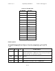
Proprietary Information TPRMTPRM ProductSpec.doc Tellus Technology, Inc. Connector Pin Out Table Pin Number Pin Name 1 PWR 2 PWR 3 GND 4 TXD 5 RXD 6 /CTS 7 /RTS 8 GND 9 TX_IND 10 RSSI 11 RESET 12 Reserved Pin Descriptions The following table describes the function of each of the connector pins. In the following descriptions, a CMOS logic low or logic 0 is < 0.8V and a CMOS logic high or logic 1 is > 4.0V. Pin Name Pin # I/O Pin Description PWR 1 and 2 I +5VDC ± 0.
Proprietary Information TPRMTPRM ProductSpec.doc Tellus Technology, Inc. /CTS 6 O Clear to send output from the modem A logic low indicates that the modem is able to accept data. A logic high indicates that the modem is not able to accept data and therefore the host should not send any data. If data is sent while this output is high, the data will not be received correctly by the modem. This is a CMOS output.
Proprietary Information TPRMTPRM ProductSpec.doc Tellus Technology, Inc. RSSI: The RSSI has a gain of +19.6 mV/dBm The RSSI is set at an RF Input = -100 dBm 1.35 V. This value is calibrated at the factory and the offset value of 1.35 V at –100 dBm is not specified, nor guaranteed. The output should be terminated into a high impedance input > 50K . 3. Software Interface The signaling between the module and the Host is provided in the following documents: 4.
TPRMTPRM ProductSpec.doc Proprietary Information Tellus Technology, Inc. The following is a description of the steps to go through to establish the modem connection: 1. Send the connection command packet to the modem. Wait until the response from the modem is received to confirm that the modem has been connected to the network. 2. Establish a socket connection for TCP, or a virtual socket connection for UDP. 3. The modem is now ready to transmit and receive data.
TPRMTPRM ProductSpec.doc Proprietary Information Tellus Technology, Inc. Warning While operating this device, the antenna for this device must be placed 20 cm or more from all persons during operation to satisfy FCC radio-frequency exposure requirements Operations at closer than 20 cm to persons must meet Specific Absorption Rate (SAR) requirements, which requires separate FCC approval.
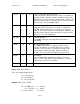
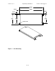
Proprietary Information TPRMTPRM ProductSpec.doc Tellus Technology, Inc. 5.240 0.125 4.990 0.245 0.125 2.25 2.000 1.760 4X Ø .128 Figure 1.