
Product Specs


TPRM ProductSpec.doc
1 of 7
1. Introduction
This document describes the specification of a CDPD module, which is designed for
system integrators that require a CDPD modem.
Section 2 describes the hardware interface for this module. The module has a serial
interface connector for the Host to communicate with. An antenna connector is also
provided for connecting to an external antenna. A standard 50Ω dipole antenna is
suggested.
The software specification are referenced in Section 3. For a detailed description, refer
to referenced documents containing the specifications. Some operation procedures are
given in Section 4. These procedures should be treated as examples for the Host
firmware developer. The mechanical specification is given in Section 5. FCC
Requirements are provided in Section 6.
2. Hardware Interface
In this section, we describe the external interface of the CDPD modem module. The
hardware interface has two parts: the antenna connector and the baseband signal
connector.
The antenna connection is a standard MMCX 50Ω connector. A 50Ω co-axial cable is
required to connect to the external antenna. A standard 50Ω dipole antenna is
recommended.
The baseband serial connector is an SMT ZIF Connector, 12 Pin, FH10-12S-1SH Hirose
(53-152310-02TEKCON) which accepts a I mm Flex Cable.
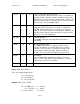
Host Interface
An asynchronous serial interface to the Host is implemented to support the
communications and data transfer between the modem and the Host. A 12-pin
connector is used to implement this serial interface. The Host should set up the serial
communication line control to match with the modem’s communication line setup. The
parameters, which must be set, include the baud rate, number of data bits, parity, and
number of stop bits. The modem parameters are 38400 baud, 8 data bits, no parity, and
1 stop bit (or more concisely, 38400 8-N-1).
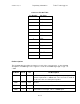
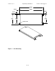
The pin assignment is shown in the connector pin out table below. Take extra
precaution to ensure that pin 1 of the mating connector connects to pin 1 of the board
connector. When looking into the connector on the TPRM unit, pin 1 is on the far right.
Also ensure that the contacts on the connector cable mate to the contacts on the
connector. The connector contacts for the TPRM are on the top, when looking into the
connector.