
User Guide


INSTALLATION | 15
Bridging impedance (10k ohms) ♦
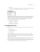
Analog Input XLR
PIN DESCRIPTION
1 Ground
2 Audio +
3 Audio -
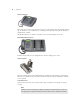
e inputs are designed to be sourced from balanced, line level signals. Usually shielded cables
have the shield wire connected only on one end to prevent ground loops. Older equipment
with a transformer output stage may need a terminating resistor across pins 2 and 3; consult the
manual for your equipment for how to use it with high impedance inputs.
When using unbalanced sources, we recommend using pin 2 and 3 to connect the signal and
ground, respectively. Usually pin 1 is not connected in order to avoid ground loops.
e sensitivity of the send inputs are adjusted using Nominal Input Level in the Audio menu.
e Input meter indicates the level after the adjustment and before the AGC. See Sections 3.3,
5.1, and 5.4 for additional information on level adjustment.
Note
The Telos Nx12 uses the currently-favored pin-outs for three-pin XLRs. You can easily remem-
ber the correct signals when wiring connectors by using the phrase “George Washington
Bridge.” Pin 1 = G = Ground, Pin 2 = W = “+” = White (typical color in mic cable, if there is no
white there will be a red conductor), and Pin 3 = B = “-” = Black.
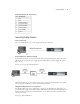
AES Digital Inputs
ese are inputs for AES/EBU format digital audio signals and are only present if the unit was
purchased with this option. e AES inputs have the following characteristics:
AES3 compliant
♦
110 Ohms ♦
Sample-rate converted, so may accept sources at any of the common rates, from 32 to 48 ♦
kHz.