Portable ISDN Digital Audio Transceiver / Mixer The Best Way to Hear from There™ User’s Manual Manual Version: 1.0 / April, 1999 (v1.2.
What you’ve got here: ZephyrExpress is a portable, one-box solution for high-quality broadcast audio remotes via ISDN. It combines a flexible stereo digital mixer, two stereo monitor mixers, coder and decoder for international-standard audio data compression, and an ISDN interface. · You can plug microphones and a headphone in one end, an ISDN line in the other, and you’re ready for instant two-way 20kHz stereo transmission virtually anywhere in the world.
Customer Service We support you... · By phone/Fax in the USA. Customer service is available from 9:30 AM to 6:00 PM USA Eastern Time, Monday through Friday at +1 216.241.7225. We’re often here at times outside of these, as well – please feel free to try at any time! Fax: +1 216.241.4103. · By phone/Fax in Europe. Service is available from Telos Europe in Germany at +49 81 61 42 467. Fax: +49 81 61 42 402. · By E-Mail. The address is: support@zephyr.com. · Via World Wide Web.
Blank Screen? If ZephyrExpress’ LEDs light when you first apply power but the LCD screen appears dark, or the LCD screen lights but no characters appear, the last user may have left its brightness or contrast at an extreme setting. To reset: p • Press the DROP button and hold that button in while turning the Edit knob clockwise to reset the backlighting. It may take a few turns. d • Press the DIAL button and hold that button in while turning the Edit knob either direction to change the LCD Contrast.
Updates How ZephyrExpress works is almost entirely determined by software. This booklet is based on software version 1.2.1. Power Supply e ZephyrExpress is powered by a separate modular power supply, which is selfadjusting to any voltage between 100 - 250 VAC, 50 - 60 Hz. It connects to a 4-pin XLR connector on the rear panel. The supply must be turned off at its switch, or disconnected from the AC line, before plugging or unplugging this XLR connector.
Repairs You must contact Telos before returning any equipment for repair. Telos Systems will issue a Return Authorization number which must be written on the exterior of your package. Be sure to adequately insure your shipment. Packages without proper authorization may be refused. US customers should contact Telos customer support at +1 216.241.7225. All other customers should contact their local Telos Dealer who will verify the problem and will contact Telos and arrange for repair.
Table of Contents More comprehensive tables of contents, with page numbers, are at the start of each section. A complete index follows section 11. Section 1: Quick Results Part I: Instant Gratification, or “How to hear stereo music on a phone line” Gather information about your ISDN line Set up the hardware Configure ZephyrExpress for your ISDN line. Call yourself (testing your unit and the line) Tune into one of our test lines Section 4: Audio Operations A console at your fingertips...
Section 7: ISDN Reference ISDN BASICS Background The Basic Rate Interface (BRI) Section 10: Schematics and Data Sheets HOW TO ORDER ISDN Section 11: Appendix ZephyrExpress ISDN Compatibility Ordering: Central Office Switches and Protocols ABOUT AUDIO LEVELS CODEC COMPATIBILITY INFORMATION Section 8: System Functions Comprehensive ZephyrExpress Compatibility List Software Updates FINDING PUBLIC ISDN SITES ZephyrExpress data ports List of Known Working SPIDs by Telephone Company The Serial Port Th
A Note From the President... Waaay back in 1984, Telos’ first product was being designed on a Radio Shack TRS-80 and the attached modem was considered to be respectably state-of-theart, operating at the impressive speed of 300 bits per second. This was nearly three times the speed of the 110 bps, twenty-five pound, phone company-issue boxes I had been using over at the local college campus to talk to the hulking IBM in the bomb-shelter basement.
Notes About this Manual e w h i c ZephyrExpress and the studio Zephyr unit share a lot of features in common, particularly in how they code audio and are connected to ISDN lines. In general, things you already know or learn here about one unit will apply to the other. We use the following symbols to draw your attention to particularly important points. t ? x Introduction DANGER! This symbol calls attention to the presence of dangerous voltages inside ZephyrExpress.
Block Diagram Introduction xi
Menu Structure Utility Menu Codec Transmit Receive Bitrate Sample Rate Compatibility Ancill Data ISDN Switch type SPID #1 SPID #2 DN #1 DN #2 MSN #1 Status Out Loop Mode MSN #2 Contacts Out Outside Line Codec Setups Panic Dial Audio System LCD Contrast Microphones LCD Backlight Click Volume Mic 1 Mic 1 POTS Volume Sensitivity Sensitivity Menu Timeout Phantom Power Phantom Power Baud Rate Low Cut Filter Low Cut Filter Set Time Test Tone Test Tone Software Limiter Bypass About...
SECTION 1: QUICK RESULTS Part I: Instant Gratification, or “How to hear stereo music over a phone line” 1-2 Gather information about your ISDN line Set up the hardware Configure ZephyrExpress for your ISDN line.
If you’re in a hurry... This part of the manual will get you started quickly. It presents answers to the questions that come up often when using ZephyrExpress. It’s not a thorough technical guide — that’s what the rest of this book is about — but a way to get you through most operating situations. If you need to put the unit in service immediately, or have experience with Zephyr or other similar ISDN codecs, this section may be all you need.
was installed exactly as specified in the ISDN order instructions found at Telos’ web site and at the end of this manual. · Have circuit information supplied by the phone company. This must include the type of switch on the circuit and the telephone number(s)1. In the US, it will probably also include two SPID numbers. In Europe, it may include MSN numbers. · Have a ZephyrExpress, a microphone, and a pair of stereo headphones or other audio monitor.
1. If you’re given two SPIDs by the phone company, enter just those numbers into ZephyrExpress. This is the most common case in North America. 2. If you’re given just one SPID, don’t enter it: instead, use the PTP setting for Switch Type. i 3. If you’re in Europe you don’t have to enter anything. However, if you’re given MSNs and want to limit which numbers ZephyrExpress will answer, enter them for those numbers.
Set up the hardware You’ll need: · A ZephyrExpress · The ZephyrExpress Modular Power Supply with an appropriate power cord for your local AC supply. The supply is self-adjusting for any voltage between 100 - 250 VAC, 50 - 60 Hz. It connects to a 4-pin XLR connector on the rear panel. The modular supply must be turned off at its switch, or disconnected from the AC line, before plugging or unplugging its XLR connector.
w WARNING! ZephyrExpress units sold in North America provide power for an external NT1. If you’re using one of these, disconnect any other power supply connected to the NT1. If both ZephyrExpress and the NT1 are providing power, both will be damaged. You can tell if a ZephyrExpress will supply power by looking at the ISDN connections: if there are two telephone jacks, it’s a North American unit and you must follow the above precaution.
h Configure ZephyrExpress for your ISDN line. HOT TIP! There are two boxes on the bottom of ZephyrExpress’ screen. If you see the word Ready in both of them, your unit is probably already configured for the ISDN line. Skip this step, and go right to “Calling Yourself” on page 1-9. i If you see the word inact in both of them, your unit is not connected to a working ISDN circuit. Recheck your connections.
U T Turn the EDIT knob three clicks clockwise, to highlight ISDN. Then tap the knob in toward the panel. The display will change to look like this: Turn the edit knob clockwise to highlight either SPID#1, DN#1, or MSN#1, depending on which type of number you entered in the form on page 1-4. The menu scrolls down as you keep turning the knob. Tap the edit knob in toward the panel again to start entering that number.
h Turn the knob to select the switch type for this line, and tap to confirm. HOT TIP! The currently-selected switch type will have brackets around it (like [PTP]). If the current switch is correct for your line, select a different type and tap the knob to confirm. Then wait a few seconds, and select the proper one and confirm. This will force ZephyrExpress to resynchronize to the line using your circuit numbers. Hold the edit knob in toward the panel for about five seconds.
u U h Press the UTIL button. A screen like this will appear. If you don’t see it, turn the EDIT knob counterclockwise. Turn the EDIT knob clockwise, to select Codec. Tap the knob towards the panel to confirm that choice. The display will change to look like this: Turn the knob one click clockwise, to select the first text line (L3 stereo* in the picture above, but the text may be different on your ZephyrExpress). Tap the knob in towards the panel to confirm. Turn the knob to select L3 Stereo*.
Set up an audio input and output Plug the microphone into the MIC 1 INPUT jack on the back panel. Plug a stereo headphone into the MON 2 OUT headphone jack on the front panel. Mic 1 Volume Mic 1 Routing Switch Monitor 2 Receive routing switch Monitor 2 Receive volume Monitor 2 Headphone Jack Monitor 2 Send volume Tap the MIC 1 routing switch until the letters AB above it light up green.
Now tap the EDIT knob toward the panel. The display will change to look like this: Using the numeric keypad, enter the local number — usually without an area code — for line 2 of this ISDN circuit. You want to enter line 2, because you’ll be calling it from line 1. If you’ve placed a manually-dialed call since turning ZephyrExpress on, that number will already be entered. You can erase it, or delete any number you enter by mistake, by turning the EDIT knob counter-clockwise.
p When you’re finished talking to yourself via ISDN, press the DROP button. The screen will change to look like this: Tap the EDIT knob to hang up. Now you’re ready to really rock! Tune into one of our test lines Our US test line originates less than a mile from the Rock ‘n’ Roll Hall of Fame, in Cleveland, Ohio. There’s always something interesting playing through it. We also maintain a European test line in Freising, Germany. Here’s how to connect to them: d Press the DIAL button.
i ISDN TIP If you can place a local call to yourself, but can’t call our test line long distance, the problem is probably with your long-distance carrier. In the US, you can switch carriers by applying a “1010” code. Instructions are in the ISDN section of this manual. Press the small gray MONITOR 2 RECEIVE routing button until the letters A and B directly above it light up. This button is located along the bottom of the front panel, above the printed words MONITOR 2 MIX.
Part II: Fast Answers to Frequently-Asked Questions This section covers common operating issues. Chances are it’ll tell you all you need to know about setting up ZephyrExpress and using it in the field. Scan through the topics now, so you’ll know what you can find here. h Of course, the rest of this manual will tell you a lot more about ZephyrExpress, teach you how to use the system more efficiently, and turn you into an all-around ISDN and audio coding guru. Please don’t ignore it.
2: How do I use the menus? u ZephyrExpress uses a series of nested menus to set how it works. To open the menu system, press the UTIL button to the right of the Edit knob. The Utility Screen, with a list of submenus, will appear: Description of Highlighted Item Scrollbar T Highlighted Item To access any menu item, turn the EDIT knob until that item is highlighted. The scrollbar moves up and down to show how far through the list you’ve gone.
right. To exit any menu, hold the EDIT knob in for at least three seconds... h 3: w 4: · or, select the · or, hold the EDIT knob in and turn it to the left: each click will take you one step back through the menu structure, until you return to the Status screen. · or ignore the menu. After a while (which can be set in the System menu) it will time out and revert to the next-highest level. icon in a submenu and tap the EDIT knob.
h 6: How do I create my own Setups and Master Setups? HOT TIP! You can capture a “snapshot” of all your current settings by using the AutoCreate function, described in step 4 below. 1. Make sure all the parameters within a menu page are set the way you want them for this Setup. Then enter the Setups submenu at the bottom of that page. It will be similar to this: 2. Enter the Action box and select Create new. This will take you to the Name box. 3. Using the keypad, enter a name for this setup.
h HOT TIP: Create an Autodial that calls a Master Setup you’ve created for a specific remote venue. Then go to the Utility: Safe Mode menu and block everything except Autodialing. The remote operator can then just press the DIAL button for (virtually) foolproof remotes. ISDN connections 7: How do I connect ZephyrExpress to an ISDN circuit? There are two telephone jacks on the left side of the rear panel. Only one of them should be connected to the ISDN line.
8: How do I manually enter a network setup? You’ll need to know the type of ISDN protocol your local phone company uses for the ISDN circuit, and any other numbers that are needed: SPIDs or Directory Numbers are required by some US installations, and MSNs by some European ones (your local phone company will have to tell you what you need). Open the Utility: ISDN menu. Select Telco, and set the protocol being used. Then enter the two SPIDs, Directory numbers, or MSNs.
Alternate test procedure This won’t test whether you’re set up properly to send audio, but does test the ISDN setup and ZephyrExpress receive circuits. 1. Press the DIAL button and select Auto... 2. In the Dial a Setup screen that appears, select either US testline* or Euro testline*. 3. Tapping the Edit knob at the Setup will select the Go! box. Tap again to configure ZephyrExpress for the test line and make the connection. w 10: Our test lines play continuous music.
Audio setup 11: How do I set ZephyrExpress for my microphones? From the Utility screen, select the Audio menu and then the Microphones submenu. Each microphone has its own submenu, where you can: w h · set sensitivity (60 dB, 45 dB, or 30 dB for various ribbon, dynamic, and condenser microphones; or line to use that input with a line-level source).
The small gray routing button next to the line 1&2 gain pot lets you turn the line off, select A B to send both inputs as a stereo pair to both codec channels, or A+B to sum both inputs to mono and send it to both channels. h 13: If you want separate gain or routing controls for multiple line-level sources, you can temporarily convert either or both microphone inputs. Use the microphone sensitivity adjustment (page 1-22), and set it for line +1 dB.
you can reach the right average level but peaks are too loud, make sure the limiter is turned on. To test the digital compression engine, verify in the Status Screen that both transmit and receive are set to the same coding method (use L3-Stereo as a generic receiver when transmitting with L3-Dual, L3-Stereo, or L3-Joint). If necessary, change the methods using the Codec submenu. Then scroll down the Codec submenu to Loop Mode, and set the mode to Near. After a few seconds, both LOCK LEDs should light.
h HOT TIP: If your phone system requires an access code to get an outside line, you can enter up to three digits in ISDN settings: Outside line prefix. This code will then be automatically applied to every call you make. If you can’t place a call, check the prefix setting. 3. Line After you tap the EDIT knob to confirm the number, the word Go! will be highlighted. Tap again to place the call... or select an option: selects one of the two separate bearer channels of an ISDN circuit.
2. Are they set to a receive coding method that matches your send method? Try changing Codec settings while they listen. 3. Try changing the Codec: Bitrate and redialing. Some connections will pass one rate but not the other. 4. If you're working in stereo, make sure both ISDN lines are connected. If one of them hasn't been dialed or has dropped the connection, they won't hear a single channel of audio — instead, they'll hear nothing at all.
19: Where do I find answers to other questions? Question Manual Section How do I order my ISDN line? ISDN information and order forms: Appendix How do I connect ZephyrExpress? Hardware Details in Section 3; also Audio Details in Section 4; How do the controls work? Hardware: Section 3 What are the meanings of all the menu items? Full Menu Reference: Section 7 Should I use Layer III, Layer II, or G.
2 2B+D · 1-2 A analog calls · 1-2, 1-25 audio setup · 1-10 Autodial · 1-18, 1-19, 1-24 B L limiter · 1-22, 1-23 Line input · 1-22 locked · 1-17, 1-20 low cut · 1-22 M menu structure · 1-17 menus, locked · 1-17 Basic ISDN · 1-2 menus, using · 1-16 BRI · 1-2 meters · 1-11, 1-12, 1-13, 1-20, 1-23, 1-25 microphone inputs · 1-23 C call yourself · 1-11 calling · 1-20 circuit information · 1-4 coding methods · 1-21 D directory number · 1-20 display · 1-7, 1-8, 1-10 DN · 1-8 microphone setup · 1-22 Micro
safe mode · 1-17 test lines · 1-9, 1-21 sensitivity · 1-22 testline · 1-21 setup · 1-5, 1-16, 1-18, 1-21, 1-24 text entry · 1-16, 1-17 SPID · 1-3, 1-4, 1-8, 1-20 troubleshooting · 1-19 status screen · 1-10, 1-20 T U interface · 1-19 test · 1-9 1-2 U QUICK RESULTS
SECTION 3 ZEPHYREXPRESS HARDWARE About our hardware...
About our hardware... ZephyrExpress, like almost everything else these days, is a software-driven device. This lets us put more features into the system, and means new updates can be installed without opening the case. But hardware’s important too. We put a lot of effort into making a system that would be compact and field-worthy, while looking and feeling like the precision audio equipment it is.
The Mixer Section Mic 1 Gain Mic 2 Gain Assign LEDS Line In Gain MIXERS: Send Routing Switches Monitor 1 Monitor 2 Monitor 2 Headphone Jack Send Mixer Mic 1 and Mic 2 Routing Switches h t Press these buttons to cycle whether each mic’s signal will be sent to channel A, channel B, both channels, and off. The letters above each button will light up in green to indicate which channels are selected. This determines which one or two ISDN transmit channels will get the signal from that microphone.
h HOT TIP! If you need line inputs with separate gain or routing controls, you can convert either or both microphones to line level: set the Audio: Microphone Sensitivity adjustments to line +1 dB. Level Controls The three large knobs, with black caps, control the send level for their respective inputs. MIC 1 and MIC 2 are mono controls; LINE 1&2 is a stereo control. Monitor Mixers Send Routing Switches h There are two of these: one for each of the two stereo monitor circuits.
Display section Send Meters Receive Meters LCD Display SAFE Indicator Locked Indicators Send and Receive Meters h h The SEND meters indicate the levels being sent to the audio encoders. This is important, because codecs work best when they’ve got a reasonably high signal to work with. Adjust the mixer so that most of the green LEDs below -10dB are lit during average program material, with the red LEDs flashing occasionally.
audio will be muted if the coded audio bitstream is corrupted because of transmission problems. LCD Display This normally displays the Status screen. Transmit Coding Method ISDN channel Data Rate Receive Coding Method Audio Sample Rate dp T l When you press the DIAL, DROP , UTIL , or HELP buttons, the screen changes to show that function. Dial, Drop, and Help are self-explanatory. Util opens ZephyrExpress’ Utility menu, where you can change system parameters.
The SAFE indicator flashes briefly when changing codec modes. If SAFE is blinking, it may mean that someone left ZephyrExpress in one of its loopback modes when they last turned the system off. Normal operation will be impossible until you use the Codec menu to turn Loopback: Off. Blinking is normal if you have a European ISDN card and aren’t connected to an ISDN circuit.
h HOT TIP The EDIT KNOB is frequently called JOG on ZephyrExpress’ screens. That’s simply because it takes less space to write it that way. DIAL button Dialing is a screen-driven software function. We’ve included complete instructions here, in the Hardware section of this manual, because the DIAL and DROP buttons don’t make any sense without it. d Press DIAL to initiate an ISDN or analog phone call. The display will show the dialing selection screen: Select Manual...
analog POTS call, as described in Section 4 (Audio Operations). Once you’ve changed one of these fields, press EDIT again. Then turn the knob to re-highlight the Go! field, and press EDIT to place the call. DROP button p w Press DROP to hang up an ISDN or analog phone call, regardless of whether you placed it or someone else called your ZephyrExpress. The display will show the drop selection screen: If only one line is in use, it will be pre-selected when the screen appears (such as Line 2, above).
Used to enter numbers for dialing, and text for setup names. Dialing works like a telephone. To enter text characters, press the key with the appropriate letter printed on it. Keep tapping it to cycle through the possible choices. For example, tapping the 2 -key in a text field will first enter A. Repeated taps will change that to a B, then C, then the lower-case letters, then the number 2. Enter a space by pressing 1 three times. Punctuation characters appear on the * and # keys.
Data connection section Note: You only need to use one of the ISDN connectors. From ISDN NT-1 Adapter From ISDN direct line Remote and Download connector SAFE switch Line sync indicator Parallel Control MODE switches SAFE MODE w Turn ON to protect menu settings against accidental changes. This switch can be turned off with a small screwdriver blade or ballpoint pen. IMPORTANT! Don’t attempt to move the SAFE MODE switch with a pencil.
w IMPORTANT! The S interface, in US versions, provides power for the NT1. Disconnect any other power supply connected to the NT1. Failure to do so will result in damage to ZephyrExpress, the NT1, or both! European units — indicated by a single ISDN connection and the Euro Telecom logo shown here — do not provide power for the NT1. You may connect these directly to a powered NT1. The S interface is a standard modular RJ-45 style jack.
w IMPORTANT! North American ISDN connections are unterminated and not protected from line surges. These surges — from lightning and other causes — can damage electronic equipment, including ZephyrExpress’ U interface. Telephone-line protectors are available from electronics and computer stores. It’s your responsibility to ensure that adequate protection is provided. Only the two center conductors (red, green) of the ISDN jack are used with a U interface.
RS-232 Pinouts h PIN FUNCTION 2 Rx (Computer to ZephyrExpress) 3 Tx (ZephyrExpress to Computer) 4 DTR (ZephyrExpress ready output) 5 Ground HOT TIP! This port is configured as DTE, not DCE. This means pins 2 and 3 are wired like a computer instead of as a modem. You can plug in a standard modem, set for auto-answer, to remotely control ZephyrExpress for automated remote broadcasting.
+5V +30V Max Parallel logic input circuit. Outputs The outputs are open-collector closures to ground, active low. They require a pull-up resistor to use with logic-circuit inputs. The pull-up may be built into the external device; if not, use a 2.2kW resistor to the port’s +5v supply. Current should be limited to 400mA for each individual output and no more than 1 amp total.
ZephyrExpress XLR connectors are electronically balanced with pin 1 ground, pin 2 hot, and pin 3 return. Line inputs are bridging, high-impedance. Outputs are active-differential balanced, at a nominal +4dBu; an external resistive pad may be necessary for consumer amplifiers. All XLR Pinouts h PIN FUNCTION 1 Ground 2 Audio + 3 Audio - · To use the line inputs with unbalanced sources, connect the signal to pin 2 and ground to pins 1 & 3.
microphones), -45dBu (most dynamic and condenser mics), or -30dBu (very hot condenser mics or dynamics in loud environments). w Either microphone input’s sensitivity can also be set to line, with a nominal level of +1dBu, for use as an additional line input. When line is selected, phantom power is not available. IMPORTANT! We don’t recommend using unbalanced microphones.
Monitor 1, Monitor 2 Headphone outputs Stereo jacks with left on the tip, right on the ring, and ground on the sleeve. Monitor 2’s front- and rear-panel headphone jacks have separate output buffers, so one can be used to drive low-impedance headphones while the other drives high-impedance ones or an unbalanced monitor amplifier.
Power Input PIN Voltage 1 +5Vdc @ 5A 2 +12Vdc @ 1.5A 3 -12Vdc @ .5A 4 System Ground Power Supply A separate modular power supply is provided with ZephyrExpress. Make sure it is not turned on, or check to make sure it isn’t connected to an AC line. Then plug its 4-pin XLR connector into the jack on the right side of the rear panel. The supply is self adjusting between 100 - 250 VAC, 50-60Hz. Power consumption is 150 Watts.
w e e w IMPORTANT: Never connect or disconnect the modular supply while it is powered! Make sure the power supply’s green LED is dark before plugging or unplugging its XLR connector. Connecting or disconnecting the modular supply while powered can erase memory settings or even damage ZephyrExpress. NOTE: WARNING! There are no user-serviceable parts in the power supply. Do not attempt to open it, as hazardous voltages may be present.
A A B switch · 3-3 Autodial · 3-8 B blank screen · 3-6 loopback · 3-7 M Manual dialing · 3-8 meters · 3-2, 3-4, 3-5 microphone inputs · 3-16 Microphone routing switch · 3-3 monitor mixer · 3-17 D N DB-9 · 3-13 diagnostic · 3-5 NT1 · 3-11, 3-12, 3-13 Dial button · 3-6, 3-8 numeric entry · 3-7 direct receive outputs · 3-17 Drop button · 3-6, 3-9 DTMF · 3-10 E Edit knob · 3-6 F front panel · 3-2 P parallel port · 3-14 Phantom Power · 3-3, 3-16, 3-17 phone plugs · 3-17 power supply · 3-12, 3-18, 3-
SECTION 4 AUDIO OPERATIONS A console at your fingertips... The Send Mixer Microphone Inputs Mic Routing Switches Line Inputs Line Routing Switch Send Level Controls SEND Meters The Monitor Mixers Monitor Routing Switches About Monitor Panning Adjusting individual monitor panning Receive Meters LOCK lights Analog (G.
A console at your fingertips... ZephyrExpress includes three separate 4-input stereo mixers, designed to make remote broadcasting easier. They incorporate both digital and analog technology, giving you the best of both worlds.
to feed a local PA system or DAT recorder, along with a rear-panel stereo headphone jack. The other monitor mixer has dual stereo headphone outputs to feed producer and talent simultaneously. If we sound proud of the design of ZephyrExpress’ mixers, we are. But if you’d prefer to bypass them entirely, there are also separate direct-codec outputs . You can use these for high-quality stereo monitoring regardless of the mixer settings.
w BEWARE THE PHANTOM! While properly-wired balanced microphones can’t be damaged by phantom power, improperly-wired ones will cause trouble. Plugging in an unbalanced mic, using a “cough button” that shorts the mic’s signal to ground, and some kinds of cable shorts can damage the microphone, ZephyrExpress, or both. If you’re not using a condenser microphone that specifically requires phantom power, leave that setting turned off.
t DEEP TECH NOTE! The limiter activity depends on the peak-to-average ratio of the program material and may appear to operate at less than 15 dB above nominal level, depending on the audio being limited. Why you might want to leave the limiter off: h · Dynamic range increases by about 7 dB, which may be desirable for nonbroadcast applications. · Total harmonic distortion and noise figures are slightly better with the limiteroff.
Line Inputs The two line inputs can be used for a single stereo or one or two mono signals.
Send Level Controls The three large black knobs control the level of their respective signals to the send bus. They are calibrated in arbitrary gray dots that don’t mean much, since the best way to mix is by using your ears and the SEND meters. SEND Meters The two 14-segment SEND level meters have a fast attack and slow decay time, to alert you to any problems in the transmitted level.
The Monitor Mixers MONITOR 1 Send Receive Routing Level Routing Level Mon 2 Routing Level Routing Level Headphone Jack Send Receive MONITOR 2 Receive Meters Lock Indicators There are two independent monitor mixers. ¥ MONITOR 1 has a stereo headphone jack and two XLR output jacks on the rear panel. Its jacks are marked with gray circles, and its knobs have gray inserts. ¥ MONITOR 2 has stereo headphone jacks on the front and rear panel.
¥ B routes the signal from the Channel B send bus to the monitor. ¥ A B routes both channel send busses to the monitor. ¥ (OFF) disconnects the send signal from the monitor. The two Monitor RECEIVE routing switches (MONITOR 1 RECEIVE, MONITOR 2 RECEIVE ) do the same thing, only with the signal from the A and B Receive Decoders. But these are stereo monitor mixers, and the individual send busses or receive channels may be mono or part of a stereo pair.
Monitor 1 Receive From Rec A From Send A Monitor 1 Send A-only Pan Select A Only From Rec B Select B Only B-only Pan From Send B Select A+B A+B A Pan To rest of Monitor 1 Circuitry A+B B Pan Adjusting individual monitor panning Scroll down the Audio settings screen and you’ll see four submenu entries, one for each of the four monitor outputs: The four submenus have identical structures: Select which setting you want to adjust by highlighting it and pressing EDIT.
You don’t have to pan mono signals to the middle: h ¥ Separating the microphones slightly to match their physical positions may make it easier to reach for the right knob when mixing a live show... even if you’re sending their signals in mono to the studio. ¥ If you need more than two separate monitor mixes, you can use the individual stereo channels as monaural mixes and pan the signals to determine which mix will hear them.
Normally both LOCK LEDs work together. If the receive mode is G.722, however, they’ll operate independently to indicate the status of individual channels. Analog (G.711) phone calls ZephyrExpress can send or receive standard analog (or POTS1) calls on either ISDN line, eliminating the need for a separate telephone and analog circuit at the remote site. The call is carried as ISDN data to the telephone company’s switching office, where it’s converted and treated as a standard connection.
h up, you’ll be able to hear the caller through the internal speaker. Otherwise, you can bring up caller audio through one of the monitor circuits as RECEIVE A or RECEIVE B, depending on which line the call came in on. HOT TIP! ZephyrExpress places most mono codec calls using the Channel A send bus and ISDN Line 1. It’s a good idea to tell analog callers to use Line 2 — or give them only that number — so Line 1 remains free. Placing calls d To place a POTS call, press the DIAL button.
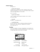
Dealing with Delay Mix-Minus All perceptual coders have too much delay for talent on remote to hear themselves via a round-trip loop. Therefore, a special mix-minus arrangement is required – exactly the same as has been used with satellite linked remotes for years. The principle is this: The remote performers do not hear themselves via the studio cue return. Rather, their microphones are mixed locally with a studio feed which has everything but the remote audio – thus the “mix-minus” designation.
REMOTE SITE Local send plus ISDN receive STUDIO Music + phone to remote Remote anncr to studio Zephyr or ZephyrExpress + Main Program Output + Telephone Mix-Minus Other Sources for music, etc. + Remote Mix-Minus Studio Console Phone Hybrid Diagram showing system set-up for remotes with delay in the transmission path and phones taken at the studio. Note that this is the same as required for satellite links. Another issue worth considering is the round trip delay.
A M meters · 4-4, 4-7, 4-11 analog circuits · 4-2 microphone inputs · 4-2, 4-3 analog phone calls · 4-12 mixer · 4-2 C mix-minus · 4-14 monitor · 4-2 coding delay · 4-14 monitor mixer · 4-8, 4-9 coding methods · 4-12 monitor output · 4-10 D delay · 4-14 G O overload indicator · 4-5 P G.711 · 4-12 panning · 4-9 G.
SECTION 5 AUDIO CODING OVERVIEW 5-2 Introduction to Audio Coding Basic Principles of Perceptual Coding 5-2 5-3 ISO/MPEG LAYER 3 5-5 Layer 3 Features Psychoacoustic Masking Redundancy Reduction Bit Reservoir Buffering Ancillary Data Layer 3 Joint Stereo 5-5 5-5 5-6 5-6 5-6 5-7 ISO/MPEG LAYER 2 5-7 Layer 2 Joint Stereo Layer 2 Mono-128 5-8 5-8 G.722 5-8 CASCADING 5-9 Mixed MPEG Layer 2 And Layer 3 Signal Chains 5-10 CHOOSING THE CODING METHOD FOR YOUR APPLICATION 5-11 Delay vs.
OVERVIEW Introduction to Audio Coding Audio takes up a lot of data. ? ? Without data reduction, CD-quality quality audio — 16 bits at 44.1kHz sample rate — requires a transmission capacity of about 705 thousand bits per second (kbps) for each audio channel. But the wires we use for remote broadcasting are on a telephone system designed for voice-grade communications: 8 bits at 7kHz sample rate, or 56kbps per channel. That’s less than 8% of what we need.
finalized in November 1992 with three related algorithms, called Layers, defined to take advantage of psychoacoustic effects when coding audio. Layer 1 and 2 are intended for compression factors of about 4:1 and 6 or 8:1 respectively, and these algorithms have become popular in satellite and hard-disk systems. Layer 3 achieves compression up to 12.5:1 — 8% of the original size — making it ideal for ISDN.
90 deciBels 60 Masker Masking Threshold 40 Masked Sound Threshold in quiet 20 Inaudible Signal 0 .02 .05 .1 .2 .5 1 2 kiloHertz 5 10 20 Masking effects in the frequency domain. A masking signal inhibits audibility of signals adjacent in frequency and below the threshold. To benefit from the masking effects, perceptual coders use a filterbank to divide the input audio into multiple bands for analysis and processing.
w IMPORTANT! Due to a perceptual coder’s reliance on precise principles of human perception, audio to be coded should not be processed with any non-linear dynamicsprocessing such as clipping, multi-band compression or limiting. Wideband compression or AGC is acceptable and may be desirable if a consistent level cannot otherwise be achieved. The same is true to audio which has been decoded after passing through a perceptual coding cycle, but to much lesser degree.
main bands into 18 more. At a 32 kHz sampling rate, the resulting bandwidth is 27.78 Hz – allowing very accurate calculation of the masking threshold values. Sufficient frequency resolution is available to exceed the width of the ear’s critical bands (100 Hz below 500 Hz; 20% of the center frequency at higher frequencies) across the audible spectrum, resulting in better hiding of noise than would otherwise be possible.
Layer 3 Joint Stereo w A joint stereo mode permits advantage to be taken from the redundancy in stereo program material. The encoder switches from discrete L/R to a matrixed L+R/L-R mode dynamically, depending upon the program content. The matrixed mode of operation takes of advantage of the usual redundancy of the “center” channel information and therefore significantly improves overall fidelity. WARNING! Joint stereo takes advantage of the way sounds distribute themselves over a normal stereo field.
Layer 2 Joint Stereo The Layer 2 joint stereo mode uses an “intensity coding” method. This method has high coding power and is quite effective, but hurts stereo separation on some program material. Audio above 3 kHz or so is combined to mono and panned to one of seven positions across the stereo stage. Layer 2 Mono-128 ZephyrExpress lets you combine ISDN channels and use the resulting 112/128kbps data stream for a single Layer 2 monaural channel.
G.722 uses a procedure called “statistical recovery timing” or “statistical framing” to lock the decoder to the data stream. (We use the procedures specified in ANSI standard T1.306-1989.) This process usually happens instantaneously, but can take up to 30 seconds. w Other strange effects may be observed. Tones and noises may be present before locking occurs, and some continuous audio tones may cause momentary unlocking. Please note this is inherent in G.
• The goal is to get as much “coding headroom” as possible at each stage. This is achieved when you: 1. Use the most possible bits at each stage, with the least possible compression (for example, by lowering the sample rate, and using 64kbps rather than 56kbps connection), and/or 2. Use the more powerful coding method of those available at each stage. At the moment, we offer the following advice: • Use coders only where necessary. Consider the alternatives at each stage.
CHOOSING THE CODING METHOD FOR YOUR APPLICATION This chart describes and compares some of the important characteristics of each method. Because ZephyrExpress includes all three popular coding methods, it’s possible to choose the most appropriate one for each application. Audio Coding Comparison Chart Layer 3 Algorithm Audio Freq. Response/mono 24 kHz sample rate, 64 kbps line 32 kHz sample rate, 56 kbps line 48 kHz sample rate, 64 kbps line 48 kHz s/r, 128 kbps line** Audio Freq.
Delay vs. Quality Looking at the chart, one thing that should be apparent is that there is a trade-off between delay and audio performance. Layer 3’s excellent audio performance requires a significant delay. This is because some of its power comes from the ability to analyze the audio over a relatively long period, and because the audio must traverse four DSPs in the encoder. Layer 2 requires the next longest delay, and G.722 has minimal delay.
w IMPORTANT! The Layer 3 decoder in L3 STEREO mode requires that both ISDN lines be connected and operating in order for the decoder to function. Until both lines are present, the decoder will not output anything, even if the transmission mode at the distant studio is not stereo. Any data drop outs would cause interruption in both audio channels. If your application requires the ability for the two channels to come and go independently, such as when they are from independent sites, you must use G.
• L2 JOINT (Joint Stereo) mode uses the “intensity coding” method in order to provide maximum quality for stereo program material. Delay is also compensated to preserve phase. Sampling Rate This option sets the sample rate for the transmitted and received coded audio. Input/output is independent and is set in the AES menus. The Layer 3 mode may be operated at either 48 kHz or 32 kHz sample rate. 48 kHz offers lower delay and 20 kHz audio bandwidth.
Compatibility Between Telos Codecs The table below shows which Zephyr or ZephyrExpress transmit and receive modes may operate with each other, the resulting audio bandwidth for each, and information which describes what happens to the audio channels when they are output from the decoder. Xmt Mode Rcv Mode Audio Resp. Notes: L3 DUAL (one Line) (Channel A) L3 MONO (Line 1) 15/20kHz* Audio appears on both outputs.
While Layer 3 is a more complex algorithm to implement and so took longer to be supported, some non-Telos boxes can now communicate with Layer 3. Our implementation follows the strict ISO/MPEG standard. ZephyrExpress’ G.722 mode offers compatibility with almost all codecs which use this coding method, and which do not use the rare H.221 framing scheme. Section 7 (Menu Reference) includes more information that may be helpful in picking a standard for compatibility.
A APT-X · 5-2 audio coding · 5-2 B bandwidth · 5-14 bit reservoir · 5-6 C J joint stereo · 5-7, 5-8, 5-12, 5-13 L Layer 2 · 5-7, 5-10, 5-11, 5-13 Layer 3 · 5-3, 5-5, 5-10 M masking · 5-3 cascading coders · 5-9 mono128 · 5-13 CCITT · 5-8 Mono-128 · 5-8 coding methods · 5-2 multi-band compression · 5-5 coding methods, comparing · 5-11 multiple codecs · 5-9 compatibility · 5-15 Musicam · 5-7 D delay · 5-12 dual mono · 5-13 dynamic range · 5-2 F filterbank · 5-4, 5-5 Fraunhofer · 5-7, 5-10 G G
SECTION 6 MENU REFERENCE The Menu System 6-2 A typical menu Navigation Shortcuts Getting HELP Menu Overview 6-2 6-3 6-4 6-5 Using Setups 6-6 Applying a Setup Creating or Changing a Setup Master Setups Applying a Master Setup Creating or Changing a Master Setup Auto-creating a new Master Setup Manually creating a Master Setup Updating an existing Master Setup Deleting a Master Setup Autodial Setups Creating a new Autodial Editing or deleting an Autodial 6-6 6-6 6-7 6-7 6-8 6-8 6-9 6-9 6-9 6-10 6-10 6
The Menu System h ZephyrExpress’ operating parameters are set through a series of nested menus, organized by function. Many menu items are “live” — changing the value makes an immediate change in ZephyrExpress’ behavior — and every item is supported by specific, unique online HELP. To find out what a item menu does (without reading this section), highlight it and press the HELP button.
• If the item is all text or numbers (such as Line sens Profess), it directly changes this operating parameter. Select it by pressing EDIT, and you can change its setting.. • If the item has an arrow icon (such as Microphones ), it opens up a submenu when you press EDIT. Here you’ll find additional choices related to the item (in this case, you can set each microphone’s sensitivity, phantom power, and so on).
h • Hold EDIT in and turn it one click counter-clockwise, to jump to the top item on any menu. In menus, this is , taking you to the next higher menu or the Utility screen. In the Utility screen, this takes you back to the Status screen. HOT TIP! The shortcut above means you can hold EDIT in and spin it many clicks counterclockwise to return to the Status screen... no matter how deep you are in the menu system. This is often the fastest way to escape from menus.
Menu Overview Utility Menu Codec Transmit Receive Bitrate Sample Rate Compatibility Ancill Data ISDN Switch type SPID #1 SPID #2 DN #1 DN #2 MSN #1 Status Out Loop Mode MSN #2 Contacts Out Outside Line Codec Setups Panic Dial Audio System LCD Contrast Microphones LCD Backlight Click Volume Mic 1 Mic 1 POTS Volume Sensitivity Sensitivity Menu Timeout Phantom Power Phantom Power Baud Rate Low Cut Filter Low Cut Filter Set Time Test Tone Test Tone Software Limiter Bypass About...
Using Setups Codec Setup Items The first text item in any menu is an automatic Setup function, which applies preprogrammed values to all the items in that menu. Setups can be preset at the factory or created by the user. Factory-built setups are indicated with an asterisk at the end of their names. Custom setups are saved through a menu item at the bottom of each menu. h In the picture above, L3 mono* is a factory-supplied setup.
Select the Action field and choose from Create new, Update, Activate, View, or Delete. Then confirm. If you’re creating a new setup, you’ll then be able to enter a name using the keypad. After you confirm the name, the Go! box will be selected. Press EDIT again to confirm, and all the current settings for this menu will be stored with that name. If you’re updating an existing setup, the Name field will display the existing setups for this menu. Select one and the Go! box will be selected.
h When you find the desired setup, press EDIT to confirm. You’ll see a confirmation screen with the message Do you really want to activate this setup? Turn EDIT to highlight Yes, and press it to confirm. You can still change individual menu items setting manually, even after applying a Master setup. HOT TIP! Auto-Dial Setups (page 10) can include a Master Setup. Then, when you select that Auto-Dial number the Maser Setup will be applied automatically.
Manually creating a Master Setup You can also create Master Setups by picking and choosing individual setups, letting the system auto-create setups only for specfic menus, and telling the system not to change other menus when the Master Setup is applied. After you select Create New and enter a setup name, the screen will scroll down to show a list of ZephyrExpress menus, such as Codec in the screen shot below: Choose a menu setup to be stored with this Master setup.
Autodial Setups The last item in the Utility screen lets you pre-program numbers for auto-dialing (see the dialing instructions in Section 3, Hardware). When you select it, you’ll see a screen like this: In the Action field, you can select Create new, Update, View, and Delete. Creating a new Autodial If you select Create New, you’ll be able to enter a Name for the setup This name will appear in the scrolling list when a user selects Autodial from the DIAL button.
Menu Details Codec menu The first item in this menu is the Codec Setup. See page 6-6. — Transmit Selects the transmit coding algorithm1: L3-DUAL L3-STEREO L3-JOINT G.722 L2-MONO64 L2-MONO128 L2-DUAL (may appear as L2-STEREO) L2-JOINT L2-HALF/24 — Receive Selects the receive coding algorithm2: L3-STEREO L3-MONO G.722 L2 L2-HALF/24 — Bitrate 56kbps or 64kpbs per ISDN channel3. Both lines will use the same rate.
i ISDN TIP! Some long-distance connections don’t support 64kbps. If ZephyrExpress won’t lock under these circumstances, both you and the distant site should change to 56kbps. — Sample Rate c 32kHz or 48kHz. Codec sampling rates can be selected for Layer III (32kHz or 48kHz) and Layer II (48kHz only). Layer II can also operate at 24 kHz using the special L2 HALF/24 transmit and receive modes. Layer III provides 15kHz audio at 32kHz sampling and 20kHz audio at 48kHz sampling.
— Loop Mode w Used for testing (see Troubleshooting, section 9) Off (Normal operation is possible) Far (Incoming ISDN immediately routed back to ISDN line) Near (Local encoded audio immediately routed to local decoder) IMPORTANT NOTE! Normal operation is impossible unless Loop Mode is Off. When this mode is on, [Loop Mode] is displayed in the upper right of the Status Screen. The level meters are disabled in Loop Mode: Far, and the middle LED of each is lit as a reminder.
— Phantom Power Applies +48vdc in a phantom configuration1. On w Off Phantom power is automatically turned off when you select Sensitivity: line. WARNING! If you apply phantom power to an unbalanced microphone, or to a mic with shorted wiring or cables, you may damage the microphone and ZephyrExpress. Don’t use phantom power unless you’re using a condenser microphone that you’re sure is wired for it. — Low Cut Filter Applies a gentle filter2 to reduce wind noise, popped plosives, and building rumble.
— Mon1 XMT pan Opens the Monitor 1 Send panning submenu. — A setting Sets how the Send A bus signal is panned when Monitor 1’s A-only routing is used. — B setting Sets how the Send B bus signal is panned when Monitor 1’s B-only routing is used. — AB setting A Sets how the Send A bus signal is panned when Monitor 1’s AB routing is used. h — AB setting B Sets how the Send B bus signal is panned when Monitor 1’s AB routing is used.
i ISDN TIP! When you confirm a change of Switch Type, ZephyrExpress tries to resynchronize the line. If you’re sure you’ve entered the correct type but the Status screen doesn’t show Ready Ready, try changing the type to something else and confirming. Then change it back and confirm again: this often fixes a balky line. i i h 6-16 MENUS — SPID#1 Service Profile Identification Number. Required only by Ntl.I-1. — SPID#2 " — DN#1 Directory Number (7 digits).
h — Panic dial Lets you choose a dialing setup to be activated when pin 7 of the parallel remote control is pulled to ground. Pin 7 must be held to ground until you want to drop the call. HOT TIP! It’s not just for panics. You can use the Panic Dial feature for automatic backup of a satellite or alternative ISDN system by connecting it to that system’s Lock output.
15 seconds 30 seconds 1 minute 5 minutes 30 minutes Never — Baud rate Sets the rate in bits per second1 for RS-232 remote control. The serial format is always 8 bits, no parity, one stop bit (8N1). See section 6, System Level functions. — System Setups See Setups, page 6-6 — Set time ZephyrExpress’ clock will keep track of the time and date in US or European styles, depending on how you enter it. To set the clock, select this item and enter the current date and time according to the instructions below.
When you select either choice, you’ll see a confirmation screen. Select Yes to reset ZephyrExpress. — About... When you select this item, you’ll see a screen like this: V1.2.1/2.36 is the version number. 16.07.1998 12:39 reflects when the software was compiled. If your ZephyrExpress’ About screen shows a lower version number, you have old software. If yours shows a significantly higher version number, this manual is probably out-of-date. In either case, contact Telos customer support.
A L access code · 6-16 line inputs · 6-14 arrow icon · 6-3 lock · 6-2 autodial · 6-10 Loop Mode · 6-13 D Dialog4 · 6-12 G G.
SECTION 7 ISDN ISDN BASICS 7-2 Background The Basic Rate Interface (BRI) SPIDS Directory Numbers (DNs) Long-Distance Digital Connectivity 7-2 7-3 7-4 7-6 7-6 HOW TO ORDER ISDN 7-7 Dealing with The Phone Company Details, Details ZephyrExpress ISDN Compatibility Protocols Ordering: Central Office Switches and Protocols National ISDN-1 (USA and Canada) AT&T Point-to-Point (Custom) (USA, Japan, Israel, some others) AT&T Point-to-Multipoint (Custom) Northern Telecom DMS100 ‘Functional’ (Custom, PVC1) (USA
ISDN BASICS Background Like just about every other aspect of our high-tech world, telephones have been making a transition from analog to digital. Digital telephone transmission services — originally intended just to make basic voice calls more cost-effective — have also made the highquality transmissions of ZephyrExpress possible.
i h ISDN TIP! While ISDN uses existing copper wires, its high frequencies mean the signal isnÕt as robust as conventional analog over those wires. How much cable there is from the telco switch or repeater is critical: in most cases, ISDN wonÕt work if the site is more than three miles from the switch. Your local telephone company must determine if a particular site qualifies on a caseby-case basis.
i t i ISDN TIP! In some cases your ISDN line will only have only one phone number for the two B channels. This is the case of the AT&T Custom PTP protocol. It shouldnÕt present a problem. The lines work as if they were on a business phoneÕs Òhunt groupÓ: the first incoming call on the number is assigned to Line 1, and the second incoming call is assigned to Line 2. Of course you have the option of which line to use on outgoing calls.
Ready Wait means incorrect SPID2 Ready Ready This is what you want to see. ISDN is working. Realtors remind buyers that the three most important factors of real-estate success are Location, Location, and Location! We want to remind you that the three most important factors to ISDN success are: Get the SPIDs, Get the SPIDs, GET THE SPIDS! i You must have these numbers, and they must be 100% correct, or the system won’t work. Don’t let the installer depart without giving them to you.
t ? DEEP TECH NOTE! SPIDs were designed to let telephone switches support different feature requirements by sensing the different identifier of each device on a BRI circuit. For example, multibutton phones could retain functions when moving from line to line. (In this case, the line number would probably not be used as the SPID.) This lets a variety of different types of equipment, with different service requirements, share a single circuit.
i commercials remind us for voice calls, you can choose an ISDN long-distance company on a per-call basis by prefixing the number with the “1010-xxx” carrier code. You must dial the full number, including the 1 or 011 + country code, following the 1010xxx numbers. ISDN TIP! If you want to temporarily switch carriers, try prefixing the call with these numbers: 1010-222 for MCI 1010-288 for AT&T 1010-333 for Sprint AT&T can be unfriendly to ISDN, and at times will block 1010 access for that service.
Bell companies offer a single point of contact number for switched digital services. Some Telcos use “Resellers” or “Agents”. If so, you should be sure to ask what experience the particular agent has with ordering lines for high fidelity audio codecs. If in doubt, go direct to the Telco. And always order your line in writing, using the ISDN order forms in the Appendix of this manual. This section is intended to be used as a reference.
NT1s The ISDN standard specifies two reference points, the ‘U’ and the ‘S’ interfaces. The U is the single-pair bare copper from the Telco central office. A device called a ‘Network Termination, Type 1’ (NT1) converts this to the two-pair S interface. In Europe and Asia the NT1 is always provided by the phone company, and only the S interface may be on user equipment. ZephyrExpress units shipped outside the USA and Canada have the S interface only.
will work with ZephyrExpress, the differences need to be taken into account when lines are ordered and the equipment set up. In the USA, telephone companies use either AT&T 5ESS, Northern Telecom DMS100, or Siemens EWSD switches. Each of these can support the National ISDN 1 (NI-1) protocol standard, which has been specified by Bellcore, the technical lab jointly owned by the phone companies.
Terminal Type: A 1010XXX: Yes Turn off features such as: packet mode data, multiline hunt, multiple call appearances, Electronic Key Telephone Sets (EKTS), shared directory numbers, accept special type of number, intercom groups, network resource selector (modem pools), message waiting, hunting, interLata competition, call waiting, etc. Get from Telco: One or two SPID numbers, depending upon number of active B channels; one or two directory numbers.
ZEPHYREXPRESS SETTINGS (FOR YOU TO ENTER): Set Switch type to: PTP SPIDs: Not required AT&T Point-to-Multipoint (Custom) Available on AT&T 5ESS CO switches version 5E6 and above. This is becoming essentially obsolete as NI-1 has the same capabilities. It is not supported by ZephyrExpress. Order AT&T Point-to-Point (Custom) or National ISDN-1 instead. Northern Telecom DMS100 ‘Functional’ (Custom, PVC1) (USA, Canada, some others) Available on Northern Telecom DMS100 switches BCS 31 and above.
Euro-ISDN (Europe, Hong Kong, some others) ZephyrExpress works with any ISDN line which conforms to the Euro-ISDN, ETS300 standard. Fortunately, this protocol is standardized and there are no further details to worry about. Bearer Service: CSD and/or CSV as desired (see above) ZEPHYREXPRESS SETTINGS (FOR YOU TO ENTER) Set Switch type to: ETS300 SPIDs: Not required. i MSNs: Two Multiple Subscriber Numbers may be provided by the telco, but are not required under normal circumstances.
1 1010-xxx · 7-7 A alternative long distance · 7-7 B ISDN ordering · 7-7 ISDN wiring · 7-3 N NT1 · 7-3, 7-9 P phone company · 7-7 bearer channel · 7-3 power supply · 7-9 BRI · 7-3 protocol · 7-9 C CSD, CSV · 7-8 D R Ready · 7-4, 7-5 S directory number · 7-11, 7-12 S interface · 7-3, 7-9 directory numbers · 7-6 setup · 7-4 DN · 7-6 SPID · 7-4, 7-11, 7-12 E Euro-ISDN · 7-10 I Inact · 7-4 Init · 7-4 ISDN basics · 7-2 7-14 ISDN T terminal type · 7-9 W Wait · 7-4, 7-5
SECTION 8 SYSTEM FUNCTIONS Software Updates 8-2 ZephyrExpress data ports 8-3 The Serial Port Communicating Security Levels Command Help Command Language Details The Parallel Port 8-3 8-4 8-5 8-6 8-7 8-12 SYSTEM FUNCTIONS 8-1
Introduction This section covers system-level functions that have aren’t part of normal audio or ISDN operations: updating the software, and using the serial and parallel ports. One other system function — setting the internal clock — is so simple that it’s covered in a few paragraphs as System menu: Set time in section 6. Actually, all of the system functions in ZephyrExpress are designed to be transparent to the user.
w 3. Select System Software: Set default. This restarts ZephyrExpress. Since the newer version was previously running (because of step 2), it becomes the default. The older version is erased from system memory. WARNING! Try new, Revert, and Set default all reboot the system. This drops any current calls, and causes ZephyrExpress to resynchronize to the ISDN line. ZephyrExpress data ports The Serial Port ZephyrExpress’ serial port lets you control ZephyrExpress’ from a modem or personal computer.
h HOT TIP! This port is configured as DTE, not DCE. This means pins 2 and 3 are wired like a computer instead of as a modem. You can plug in a standard modem, set for auto-answer, to remotely control ZephyrExpress for automated remote broadcasts.
• The terminal program’s baud rate settings. If you have the latter problem, you will probably see some “garbage” text. Verify the setting in the System: baud rate item (default is 9600 baud), or try different rates at your computer. • COM port selection at the computer. ZephyrExpress echoes any data sent to it, to verify proper operation: If a connection is properly made, anything you type will be returned to you.
To log in, wait for the prompt. Then type login followed by the password for the desired level and press Enter: >>login user ¶ If it recognizes the password, ZephyrExpress will respond with: Welcome to ZephyrExpress control system user level. w Press ? for help. >> WARNING! If ZephyrExpress does not respond to user or expert when you try to log in, somebody changed your password. You can’t change it back without knowing the new one.
The reply will always take the same format: • The first line is the name of the command ZephyrExpress is describing. • The second line is the argument — a word or number that modifies the command. Anything within brackets [ ] is optional. Some commands have the entire argument within brackets; if you send this command without an argument, it will report the present value. So if you just sent baud and Return, ZephyrExpress would send back the current communication rate.
w WARNING! baud changes the port speed as soon as you send Return. You must immediately change your terminal program’s speed to match, or communication can’t continue. bye conn c none Log out from ZephyrExpress control system. Example bye ¶ No commands will be accepted until the next logon. <1|2> Using line 1 or 2, place a call to number. Example conn 1 2417225 ¶ Place an ISDN call to 241-7225 on line 1. Hypens and parentheses in the phone number are optional.
t DEEP TECH NOTE! Remote control values for LCD contrast and backlighting are only vaguely related to the 0-100% settings in the System menu. Display current encoder input & decoder output level, for testing the meter calibration. level none log [ ] login logout metertest Used for remote debugging. During a support call, we may ask you to send this command and tell us what the result is. [ | Display current security level.
kept. [] Sets the ISDN bitrate to 56kbps or 64kbps, or keeps the current value. [] Sets the audio sample rate to 32kHz or 48kHz, or keeps the current value. You must specify all four arguments. Example mop - l3mo br64 sr32 ¶ passwo w [] Set the receive mode to L3-mono, the bitrate to 64kbps, and the sample rate to 32kHz. Leave the transmit mode alone. Change password for current security level.
In addition, Expert level includes these commands: numbase Set default number base to either decimal, hexadecimal, binary or none. If none is selected all numbers must be preceded by explicit specifiers. The default base can always be overridden by explicit specifiers: t % for binary $ for hex # for decimal numbers. DEEP TECH NOTE! Numbase is provided for users who want to write their own control software.
The Parallel Port ZephyrExpress’ parallel port has five contact-closure outputs and four logic or contactclosure inputs. Voltages and connection details are in Section 3, Hardware. Parallel Port PIN FUNCTION PIN FUNCTION 1 Ground 9 N/C 2 Output 2 10 Output 0 3 Status Out 11 Output 1 4 Output 3 12 N/C 5 N/C 13 Input 2 6 Input 3 14 Input 1 7 Input 0/Panic Dial 15 N/C 8 +5 volts 400 ma max. One of the five outputs, pin 3, is used to report successful connections.
C codec mode · 8-9 , 8-9 D DB-15 · 8-12 DB-9 · 8-3 diagnostic · 8-5 G G.
SECTION 9 TROUBLESHOOTING First Steps 9-2 GENERAL 9-3 Thinking About Problem Solving Diagnostic Aids Look into the Lights LOOPBACK modes Some Error Conditions No functionality; the box is totally or partly dead.
First Steps You don’t want to be reading this. Chances are, you reached for these pages because something isn’t working the way you expect it to. Cheer up. Most ZephyrExpress and ISDN problems are easily resolved, either by yourself or with the help of the telephone company. Unless you see blue smoke pouring out of the unit, these pages are probably all you’ll need to get running again. And if they aren’t — or if you do see blue smoke — you can always contact Telos Customer Service at h i • +1 216.241.
i i ISDN TIP! You can check ISDN continuity with an ordinary telephone or pair of 600 ohm headphones. Disconnect ZephyrExpress, and briefly place the phone (or phones) across the line. You should hear a rhythmic clicking — about once per second — or a loud, continuous white noise. If you hear a dial tone, it’s not an ISDN line. If you don’t hear anything, the line is dead.
3. Round up the usual suspects; 4. Generate a hypothesis; 5. Generate an experiment to test the hypothesis; 6. Fix the problem; Then, repeat, if necessary, to attack additional problems. Let’s cover each step of the troubleshooting sequence in detail. • Step 1. Observe the behavior to find the apparent bug. In other words, determine the bug’s symptoms. Remember always that many problems are subtle and exhibit themselves via a confusing set of symptoms.
Other Ideas Constantly apply sanity checks. Almost thirty years ago, the Firesign Theater put out an album called “Everything You Know is Wrong”. Use that as your guiding philosophy in troubleshooting a Zephyr set-up. For example, just because you checked the Telco line last night and it was fine doesn’t mean it’s OK now. At 3:00 AM when the problems seem intractable and you’re ready to give up engineering as a career, remember that the system has worked and will work again.
this way, you’ve probably got a software problem... but there’s a possibility something has gone wrong with the hardware. If the LEDs light up but you can’t see any text on the LCD display, the most probable cause is that someone left the backlighting or contrast at an inappropriate setting. p Press the DROP button and hold that button in while turning the EDIT knob clockwise to reset the backlighting. It may take a few turns.
Block diagram of the audio circuitry during Far Loopback In Far Loopback, you should be able to: 1. Route the mic to one or both send circuits; 2. Shout into the mic, and see the A or B routing LED turn red to indicate overload1; 3. Turn off the Monitor 2 SEND switch, set its RECEIVE switch to AB , raise the level, and hear the microphone in a headphone plugged into the front panel.
Near Loopback for codec testing When the Codec: Loopback menu item is set to Near, incoming audio gets coded in the usual manner, sent into the ISDN interface but then looped directly back to the decoder. This checks over 90% of ZephyrExpress’ functionality with no ISDN line present. w c ? IMPORTANT NOTE! If you are using the European ISDN TA and aren’t connected to an active ISDN line, you will hear dropouts in the audio signal during Near Loopback. This is not a problem with the equipment.
When Near Loopback is engaged and the coding methods match, the LOCK LEDs should light. Audio can be routed to the send bus, and monitored through the RECEIVE routing switches. Normal coding delays will be present. In Near Loopback, you should be able to: 1. Route the mic to one or both send circuits; 2. Shout into the mic, and see the A or B routing LED turn red to indicate overload; 3. Raise the mic’s level and see it on the send meters; 4.
• If either unit can lock to itself, consistently, while looping through the other unit’s Far Loopback, then the ISDN connection is good. • If neither unit can lock to itself then the ISDN connection is failing somewhere. This can be because some part of the connection doesn’t support the bitrate you’ve chosen. It can also happen in the unlikely event that both codecs are broken. Using two Far Loopback tests, to check units at both ends, will often tell you exactly where a problem lies.
During the initializing period, a self-test is performed. If there is a problem, this is reported on the LCD and progress is halted. The message should be noted for discussion with Telos customer support. If the unit does not reach the INITIALIZING stage, suspect a problem with the system processor, system clocks, or EPROMS Condition: ISDN Connecting OK, But No Audio What is the state of the LOCK LED? Check the LOCK LED. On means you’re connected and receiving valid data.
Condition: No Audio In Both Directions Does ZephyrExpress’ loopback isolate the problem? See above for tips on using the loopback modes. Is the ZephyrExpress mode set properly? Your Codec: transmit mode must match their receive mode. Their transmit mode must match your Codec: receive mode. Sometimes cycling between modes can clear a decode problem. h Is audio properly connected and configured? Do the loopback tests described earlier. Make sure the audio menu settings are correct.
Some mics — and many direct boxes and press feeds — will choke if phantom power is turned on when they don’t expect it. Send gain set OK? With Audio: Limiter turned off, check the SEND meters for proper indication. The top two LEDs shouldn’t be lighting at all. Do the sample rates match? If the rates don’t match — if one codec is set to 48kHz and the other to 32kHz — the signals will be transposed about half an octave and drop out every few seconds.
setup or SPIDs haven’t been entered. Init Init can also appear when a European ISDN connection has been idle for a while. This is normal, and Ready will appear when you start using the connection again. i Ready Init means only one working ISDN channel Ready Wait means incorrect SPID2 Ready Ready This is what you want to see. ISDN is working. ISDN TIP! If you see Ready Ready when the switch type is set to PTP, and you cannot dial, it’s likely that your line is really National ISDN-11.
they may have given you a 2 B-channel AT&T “Custom Point to Multipoint” line with 2 phone numbers and 2 SPIDS. ZephyrExpress does not support this configuration. If you have Custom Point to Multipoint, you can often get things working temporarily by following these steps: 1. Remove both SPIDS and both directory numbers 2. Set Switch Type to PTP 3. Have the distant codec call either of your phone numbers twice: that is, they should dial one of your ISDN numbers, drop the line, and then dial it again.
h i HOT TIP! If you suspect the SPIDs given you are wrong, or the basic line provisioning (configuration) is incorrect, call the Telco and ask them to verify the SPIDS and provisioning from the switch. They’ll probably need to have someone call you back. Verify this person is logged into the switch. Get their fax number and fax them ZephyrExpress’ ISDN information from the Appendix of this manual. Sometimes the information in the Business Office computer is wrong.
You should also try the call at different bit rates (56/64 Kbps): that can affect how the call gets routed through the network. What does the ISDN “Cause” phrase say? This phrase or something similar will appear on the LCD after dialing. It comes directly from the telephone company equipment and can be valuable for troubleshooting. Generally these phrases are self-explanatory. Getting a Cause phrase means you are at least talking to the Central Office equipment.
h • Terminal Error. Lights red to indicate a problem on the terminal (ZephyrExpress) side. Could be a problem with the cable or with ZephyrExpress itself. • Line Error. Lights red to indicate a problem with the Telco line. This means a very basic kind of problem; usually no physical connection. HOT TIP! You can use an analog phone, high-impedance headphones, or a telephone “butt” test set to do a basic check of ISDN lines: You should hear a clicking sound or white noise. If you don’t, the line is dead.
Note that in some cases there may be more than one meaning. This can frequently be evaluated by whether the message has been received by the calling party or the called party. Cause No. 1 - Check number, redial This cause indicates that the called party cannot be reached because, although the called party number is in a valid format, it is not currently allocated(assigned). Cause No.
called user or by the network. In the case of user determined user busy it is noted that the user equipment is compatible with the call. Cause No. 18 - No far end response This cause is used when a called party does not respond to a call establishment message with either an alerting or connect indication within a prescribed period of time. Cause No.
Cause No. 30 - Result of a STATus ENQuiry/Special Intercept announcment:# unassigned This cause is included in the STATus message the user sends to the switch when the reason for generating this message was a prior receipt of a STATus ENQuiry message or This value indicates that a user from outside a special business group (i.e. Centrex) has dialed a number associated with the business group which is unassigned. Cause No. 31 - Network disconnect/Special Intercept Announc.
Cause No. 47 - Resource unavailable This cause is used to report a resource unavailable event only when no other cause in the resource unavailable class applies. Cause No. 50 - Requested facility not subscribed This cause is used to report that the cannot use this feature because s/he has not subscribed to it. Cause No. 51 - Bearer capability incompatible with service request This cause indicates a user request for action was rejected because the action was incompatible with the capability of the call.
Cause No. 97 - Message type nonexistent or not implemented This cause indicates the equipment sending this cause received a message with a message type it does not recognize because the message is undefined, or it is defined but not implemented by the equipment sending this cause. Cause No.
A audio problems · 9-11 C Customer Service · 9-2 D M Maalox · 9-3 N NT1 · 9-17 P diagnostic · 9-20 phantom power · 9-13 directory number · 9-15 power supply · 9-10, 9-17 E error message · 9-13 I R Ready · 9-14 S Inact · 9-13 S interface · 9-17 Init · 9-13, 9-14 self-diagnostics · 9-5 ISDN “Cause” · 9-17 setup · 9-4, 9-14 ISDN analyzer · 9-18 SPID · 9-15 ISDN continuity · 9-3 ISDN problem · 9-13 L Layer 3 · 9-11 loopback modes · 9-6 T troubleshooting · 9-1, 9-4 U U interface · 9-17
SECTION 10 SCHEMATICS and DATA SHEETS SCHEMATICS and DATA SHEETS 10-1
SECTION 11 APPENDIX ABOUT AUDIO LEVELS 11-2 “Nominal” Levels Level, Gain, dBu and dBm 11-2 11-2 CODEC COMPATIBILITY INFORMATION 11-3 Comprehensive ZephyrExpress Compatibility List 11-5 FINDING PUBLIC ISDN SITES 11-7 List of Known Working SPIDs by Telephone Company Ameritech Bell Atlantic Bell South Cincinatti Bell Fort Mills Telephone GTE Northern Pittsburgh Telephone Nynex Pacific Bell SNET (Southern New England Telephone) Southwestern Bell Sprint/Centel US West 11-9 11-9 11-9 11-9 11-9 11-9 11
ABOUT AUDIO LEVELS “Nominal” Levels The following will help to understand what we mean by nominal: A mixing console has its analog VU meter calibrated so that a test tone set to the 0 dB red-green junction outputs +4 dBu to ZephyrExpress. The mixer is adjusted so that the VU meter looks “normal” on a music or voice program. A nominal +4 dBu is being sent to ZephyrExpress. Level, Gain, dBu and dBm We use dBu, rather than dBm, when describing both input and output levels.
100Ω +4 dBu +4 dBu 20kΩ 100Ω Here, the output is loaded with a high impedance, as would be the case with modern equipment. ZephyrExpress’ voltage level is conveyed to the load with no noticeable attenuation. 100Ω +1.5dBu +4 dBu 600Ω 100Ω When a 600 Ω load is used, the voltage divides, with 2.5 dB being lost in ZephyrExpress’ internal source resistance. Note that, in this case, the meter across the 600 Ω resistor can be said to be indicating dBu or dBm.
CCS CCS CCS CCS CCS — COMREX — INTRAPLEX CDQ2000 CDQ1000 CDQPrima Roadrunner Micro 56 DX200 DXP/DXR 4400 Micro 64 NEXUS LAYER 3 N/S N/S YES YES N/S N/S N/S N/S J-STEREO YES N/S YES N/S N/S YES N/S NO DUAL YES N/S YES N/S N/S YES N/S N/S MONO YES YES YES YES N/S YES N/S N/S 128 MONO YES N/S YES YES N/S YES N/S N/S G.722 N/S YES YES YES YES YES YES N/S LAYER 2 GENERAL NOTES: • YES = Compatible with ZephyrExpress. • N/S=Not supported by other codec.
AEQ — DIALOG 4 — GLEN ACD3001 MUSICTAXI REPORTER SOUND LAYER 3 NAGRA ARES-C RE PHILLIPS YouCom 660/661 Baby Blue ReporterSet N/S LIMITED MONO N/S N/S N/S N/S N/S J-STEREO N/S NO NO N/S NO see note N/S N/S DUAL N/S NO NO N/S NO see note N/S N/S MONO YES NO NO N/S YES YES YES YES 128 MONO N/S NO NO N/S NO NO N/S NO G.722 YES YES YES YES YES YES YES YES LAYER 2 DIALOG4 NOTE: • ZephyrExpress can transmit to DIALOG4 in the modes indicated.
L2-Mono@24 : must be set to ISO bitstream. L2-Stereo : L2-M128 : G.722 : yes! ZephyrExpress can always receive. CDQ must have H.221 switched off in order to receive from ZephyrExpress • • CCS CDQ2001 CCS Prima Prima: Front panel option decoder/general/indep=yes Or serial port command "din yes". Sample rate set to 48kHz L3-Mono : (some units have layer III and are compatible) L3-Stereo : (some units have layer III and are compatible) L2-Mono@48 : yes! L2-Mono@24 : yes! L2-Stereo : yes! L2-M128 : yes! G.
L2-Stereo L2-M128 G.722 • : : : ? ? ? PKI G.722 phone G.722 : no? Because of H.221 and SETUP indicator. • • Philips MPR Baby Blue Baby Blue : Must be switched to “CCS compatibility” mode for modes that use both B-channels (stereo, mono128) L3-Mono : - yes! yes! RE L3-Mono L3-Stereo L2-Mono L2-Stereo splitting. L2-M128 G.722 : : : : yes! no. Wrong channel : : no. See stereo. ? Telos Zephyr (rack-mount) L3-Mono : Of course, yes! L3-Stereo : Some rack-mount Zephyrs are mono-only.
• Telos World Wide Web site http://www.zephyr.com will connect you to a variety of information about ZephyrExpress and ISDN, including site pointers. • Audiobahn A list of broadcasters and sound studios using codecs, maintained by Jay Rose’s Digital Playroom, a broadcast promo studio in Boston. These sites have submitted their names so other professionals can call them for newsfeeds, help with remotes, audio transfers, and so on. All services are optional, and fees are negotiated by the parties involved.
List of Known Working SPIDs by Telephone Company Your SPIDs may be different! The phone company can assign any darned thing they want to as a SPID... but they usually adhere to these standards. Note, for each line there is only one configuration which will work. Your SPID is distinct from your telephone number and does not necessarily contain your area code or telephone number (although this is generally the case).
GTE XXXYYYZZZZ0101 — or — 01YYYZZZZ000 — or — XXXYYYZZZZ00 — or — SPID1 XXXYYYZZZZ01 SPID2 XXXYYYZZZZ02 Northern Pittsburgh Telephone XXXYYYZZZZ000 SNET (Southern New England Telephone) 01YYYZZZZ00 Southwestern Bell XXXYYYZZZZ0101 — or — 01YYYZZZZ000 — or — 01YYYZZZZ00 — or — XXXYYYZZZZ01 Sprint/Centel Nynex See BellAtlantic Pacific Bell XXXYYYZZZZ0101 — or — SPID1 XXXYYYZZZZ01 SPID2 XXXYYYZZZZ02 — or — 01YYYZZZZ000 — or — SPID1 XXXYYYZZZZ1 SPID2 XXXYYYZZZZ2 — or — XXXYYYZZZZ00 — or — XXXYYYZZZZ XXXY
From the perspective of the telephone network, each channel appears to be a separate line with its own number and independent dial-out capabilities. Since each has to be dialed or answered separately, they appear to be “lines” to users also. We refer to a B channel as a “line” on ZephyrExpress menus. ZephyrExpress’ internal interface (sometimes called by its generic name “Terminal Adapter”) is used to connect to digital ISDN telephone lines.
Pacific Bell 800-4PB-ISDN (800-472-4736) http://www.pacbell.com For questions or assistance 403-944-8130 SNET 800-420-4736 http://www.ntplx.net Stentor (Canada) Fax server 800-578-4736, document #200 has list of local ordering numbers. 403-944-8130 (questions/assistance). Southwestern Bell 800SWB-ISDN (800-792-4736) http://www.sbc.com US West http://www.uswest.
SPIDs Service Profile Identification (SPID) numbers are required in all but one the AT&T protocols. This number is given to the user by the phone company and must be entered correctly into ZephyrExpress in order for the connection to function. SPIDs usually consist of the phone number plus a few prefix or suffix digits. There is frequent confusion between phone numbers and SPIDs, even among telco personnel. While the SPID frequently includes the corresponding phone number, this is not necessarily the case.
If you find that you have the 56 kbps limit on your line, you might want to request the Telco to upgrade the “RBOC-to-IXC tandem” circuit. NT1s The ISDN standard specifies two reference points, the “U” and the “S” interfaces. The U is the single-pair bare copper from the Telco CO. A device called a “Network Termination, Type 1” converts this to the two-pair S interface. In Europe and Asia the NT1 is always provided by the phone company, and only the S interface may be on user equipment.
The Faxable ISDN Order Form (for use in US only) The following three pages can be copied, filled out, and faxed to the phone company to order an ISDN line. They should give the phone company all the information they need. The majority of installations, if ordered in writing, with this information, go smoothly. If you do experience problems Telos Systems customer support is available to assist you.
FAXABLE ISDN BRI LINE ORDER FORM Page 1 of 3 To:______________________________________________________ Telephone Company Attention: From: Location for line: Company: Company: Address: Address: City/State/ZIP: City/State/ZIP: Phone: Phone: Contact: Contact: Long distance carrier: Date needed: Termination Date (if known: We request an ISDN Basic Rate Interface (BRI) line for use with a ZephyrExpress hi-fidelity audio codec. This device is used to transmit audio using digital telephone services.
Fax page 2 of 3 PROTOCOL: National ISDN-1 From AT&T 5Ess, Northern Telecom DMS100, and Siemens EWSD.
Fax page 3 of 3 Number Display: No Call Appearance Pref:Idle 10XXX Long Distance Prefix: Yes Turn off features such as: packet mode data, multiline hunt, multiple call appearances, Electronic Key Telephone Sets (EKTS), shared directory numbers, accept special type of number, intercom groups, network resource selector (modem pools), message waiting, hunting, interLata competition, etc.
A analog levels · 11-2 Audiobahn · 11-8 C compatibility · 11-3 CSD/CSV · 11-13 D Digifon · 11-8 ISDN finding sites · 11-7 ISDN order form · 11-16 ISDN ordering · 11-10 L line input/output · 11-2 Long Distance · 11-14 P phone company · 11-10 phone company contact info · 11-11 protocol · 11-12 E S EdNet · 11-8 SPID · 11-13 I SPIDs by telephone company · 11-9 IOC · 11-12 APPENDIX 11-19