
User's Manual


BSR75 USER AND
INSTALLATION
MANUAL
Code: D198N61_DDS06
Date: 15/07/09 Page: 13 of 16
01.01.00/1 Rev.1
6.3.
ANTENNA CONNECTION
Choose the most adaptable antenna for the installation. The antenna must
have an impedance of 50 ohms to the equipment transmission frequency.
Install the antenna in accordance with the manufacturer’s instructions.
Use a coaxial cable, avoiding as much as possible large cable lengths. Cable
impedance is 50 ohms.
Measure the VSWR of the installation. Never accept a VSWR greater than 2.
If a duplexer module or a band pass filter is required, adjust them to the
working frequency before starting up.
6.4.
SWITCHING ON THE BSR75
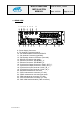
Check the connections between the modules.
Check that the power supply source is connected correctly.
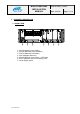
Check that the RF SMB cables are connected correctly (see Rear View
diagram Ref. 10).
Check the connections of the antennas in the RPA75 and RRX modules.
Check the 50Ω load is connected to the rear TNC connector in the RPA75.
Check that the RPS75 module LED SUPPLY is on.
Activate the power on switch on the RPS75 module.
Check that the 26.4V LED and 13.2V LED on the RPS75 module are on and
check that the LEDS “ON” are switched on in the other modules.
Wait for the BSR75 to start up.
Note: See subclause 5.3 for more information on references for the different
modules and LEDs.