
User's Manual


BSR75 USER AND
INSTALLATION
MANUAL
Code: D198N61_DDS06
Date: 15/07/09 Page: 14 of 16
01.01.00/1 Rev.1
7. CONFIGURATION
A BSR75 is configured via an NMS (Network Management System). To configure
the BSR75, consult the NMS manual.
8. INCIDENTS
The repeater must be repaired by authorized technical personnel only. If a
BSR75 failure occurs, the entire BSR75 must be replaced. If transmitter
module is damaged and there is not an entire BSR75 available to replace, set
RTX75 and RPA75 modules previously calibrated jointly. In last case and if is
not possible to carry out one of the two previous options, replace one of these two
modules and make the gain calibration again.
If an error or alarm occurs in the BSR75, this is indicated in the corresponding LED
for each one of the modules. The following list shows the possible failures and their
solutions.
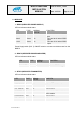
8.1.
ALARMS
Led
indication
Status
Failure / Solution
RPS75
SUPPLY OFF
Power supply failure. Check that the source and the
power supply cable are correctly connected. Check the
internal fuse of the RPS75.
Contact Technical Services if
unsolved.
26.4V OFF Power supply failure. Contact Technical services.
13.2V OFF Power supply failure. Contact Technical services.
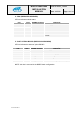
RPA75
ON OFF Power supply failure. Contact Technical Services.
TX POWER OFF
No power transmission in the antenna. Wait for BSR75
to be started up. Check other LED indications. Contact
Technical Services if unsolved.
!