
User's Manual

BSR75 USER AND
INSTALLATION
MANUAL
Code: D198N61_DDS06
Date: 15/07/09 Page: 9 of 16
01.01.00/1 Rev.1
5.3.
MODULES
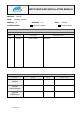
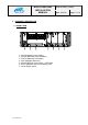
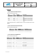
1.- RPS75 (REPEATER POWER SUPPLY)
LEDs to indicate module status.
LED TYPE NORMAL
STATUS
FUNCTIÓN
SUPPLY Green On There are 26.4V at the RPS75
input
26.4V Green On There are 26.4V at the RPS75
output
13.2V Green On There are 13.2V at the RPS75
output
Power Supply switch (Ref. 7): ON/OFF switch to connect to and disconnect from the
BSR75.
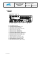
2.- RPA75 (REPEATER POWER AMPLIFIER)
LEDs to indicate module status.
LED TYPE NORMAL
STATUS
FUNCTIÓN
ON Green On Power supply correct
TX POWER Green On Module transmitting
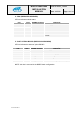
3.- RTX75 (REPEATER TRANSMITTER)
LEDs to indicate module status.
LED TYPE NORMAL
STATUS
FUNCTIÓN
ON Green On Power supply correct
REF. ERROR Red Off Failure in the 10 MHz reference
INT. ERROR Red Off Internal failure
BBSR ERROR
Red Off Communication failure with the
RCPU module
RPA ERROR Red Off RPA75 failure
RPW ERROR Red Off Reflected power failure