
Installation Instructions


56025001 Page © 2003 Telular Corporation
8
2.7 DIAGNOSTIC AND STATUS LEDS
Six LEDs are provided as a useful aid during installation and give installers an immediate visual indication
of system status.
LED Function Table – Normal Operating Mode (J5 = OUT)
LED Symbol Color Duty Cycle Indication
Solid On Unit is registered with the message center and enabled
Off Unit not registered with message center (and disabled)
Registration
LED 5
Green
Flashing Unit is registered but disabled
OFF
ALL OK
1 Flash* System Trouble Condition – Low/Missing AC Power
2 Flashes* System Trouble Condition – Low/Missing Battery Condition
3 Flashes* System Trouble Condition – LFC
4 Flashes* System Trouble Condition – NSC
5 Flashes* System Trouble Condition – RFC
STC - LED 4
RED
6 Flashes* System Trouble Condition – DTF
Off
C/C on hook
HOOK STATUS – LED
3
Yellow
Fast Flash C/C off-hook to transmit signals over cellular.
Solid ON Telguard waiting for acknowledgement from Communication Center Acknowledgement –
LED 2
Red
OFF Not processing alarm signals
OFF TG-5 initialized LED 1 Green
On TG-5 initializing
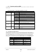
2.7.1 LED Signal Strength Indication
The Telguard provides the installer with an easy to use LED radio signal strength indicator (RSSI) for
positioning the unit or remote antenna to obtain the strongest RF signal possible. A signal strength reading
can be obtained at any time there is power applied to the Telguard without affecting the operation of the
unit. When the “RSSI” jumper J10 is “IN”, the Telguard displays the current received signal strength
within 5 seconds. The signal strength is read from Left to right using the four sequential LEDs located on
the top right side of the printed circuit board with the Radio TX LED = 1 and the AC POWER LED = 4.
RSSI Value LED’s Lighted RF dBm
NO SVC LED 1* = on, LED 2-4 = off
≤ -114 dBm
0 LED 1 = on, LED 2-4 = off
≤ -111 dBm
1 LED 1 = on, LED 2 = slow flash
LED 3-4 = off
≥ -110 dBm
2 LED 1-2 = on, LED 3-4 = off
≥ -100 dBm
3 LED 1-2 = on, LED 3 = slow flash
LED 4 = off
≥ -90 dBm (Minimum signal
strength required)
4 LED 1-3 = on, LED 4 = off
≥ -80 dBm
5 LED 1-3 = on , LED 4 = slow flash
≥ -70 dBm
6 LED 1-4 = on
≥ -60 dBm