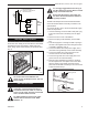
INSTALLER/CONSUMER SAFETY INFORMATION PLEASE READ THIS MANUAL BEFORE INSTALLING AND USING APPLIANCE WARNING! IF THE INFORMATION IN THIS MANUAL IS NOT FOLLOWED EXACTLY, A FIRE OR EXPLOSION MAY RESULT CAUSING PROPERTY DAMAGE, PERSONAL INJURY OR LOSS OF LIFE. FOR YOUR SAFETY Installation and service must be performed by a qualified installer, service agency or the gas supplier.
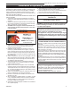
RDVN Series Direct Vent Gas Fireplace Table of Contents PLEASE READ THE INSTALLATION & OPERATING INSTRUCTIONS BEFORE USING THIS APPLIANCE. Thank you and congratulations on your purchase of a CFM Corporation fireplace. IMPORTANT: Read all instructions and warnings carefully before starting installation. Failure to follow these instructions may result in a possible fire hazard and will void the warranty. Installation & Operating Instructions General Information, Warnings, Cautions..............................
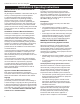
RDVN Series Direct Vent Gas Fireplace Installation & Operating Instructions This gas fireplace should be installed by a qualified installer, preferably NFI or WETT (Canada) certified, in accordance with local building codes and with current CSA-B149.1 Installation codes for Gas Burning Appliances and Equipment. For USA Installations follow local codes and/or the current National Fuel Gas Code. ANSI Z223.1/NFPA 54. FOR SAFE INSTALLATION AND OPERATION PLEASE NOTE THE FOLLOWING: 1 .
RDVN Series Direct Vent Gas Fireplace Installation & Operating Instructions Requirements for the Commonwealth of Massachusetts All gas fitting and installation of this heater shall only be done by a licensed gas fitter or licensed plumber.
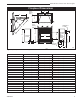
RDVN Series Direct Vent Gas Fireplace Fireplace Dimensions Rough Opening Depth S E P F S R O - Rough Opening Width Rough Opening Height Q Centerline of 7" Collar C L B N D C Gas Line Access M J Electrical Access Low Voltage Electrical Access Ref. A B C D E F G H I J K L M N O P Q R S 20007628 H J A Gas Line Access K L G Fig. 1 Fireplace specifications and framing dimensions.
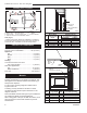
RDVN Series Direct Vent Gas Fireplace Locating Your Fireplace V W X Y Y A E Z B X C A Y B C D E Fireplace D X B Top Louvre Assembly F Top of Combustion Chamber LU584-T Fig. 2 Locate gas fireplace. LU584-R unit - Locating **Island 2/23/01 sta A - Flat on wall B - Cross corner C D - Room divider E - Flat on wall corner F - Chase installation Y - Refer to “Clearance to Combustibles” Section Note (Fig.
RDVN Series Direct Vent Gas Fireplace Hearth Final Finishing A hearth is not mandatory but is recommended for aesthetic purposes. We recommend a noncombustible hearth which projects out 12” (305 mm) or more from the front of the fireplace. Cold climate installation recommendation: When installing this unit against a non-insulated exterior wall or chase, it is mandatory that the outer walls be insulated to conform to applicable insulation codes.
RDVN Series Direct Vent Gas Fireplace Gas Line Installation When purging gas line, the front window frame assembly must be removed. 1. The gas pipeline can be brought in through the rear of the fireplace as well as the bottom. Knockouts are provided on the bottom behind the valve to allow for the gas pipe installation and testing of any gas connection.
RDVN Series Direct Vent Gas Fireplace It is strongly suggested that the wiring of the EB-1 Electrical Junction Box be carried out by a licensed electrician. Remote ON/OFF Switch or Thermostat or Remote Control Ensure that the power to the supply line has been disconnected before commencing this procedure. TP TH TP Gas Control Valve The EB-1 Electrical junction box has been fitted standard on this model to allow for the easy connection of an optional fan kit.
RDVN Series Direct Vent Gas Fireplace General Venting Your fireplace is approved to be vented either through the side wall, or vertical through the roof. • • • • 10 Only CFM Corporation venting components specifically approved and labelled for this fireplace may be used. Venting terminals shall not be recessed into a wall or siding. Horizontal venting which incorporates the twist lock pipe must be installed on a level plane without an inclining or declining slope.
RDVN Series Direct Vent Gas Fireplace General Venting Information - Termination Location INSIDE CORNER DETAIL G V H A N N D L V E C B V F B ����� ������ B V Ope ra Operable ble V B B B V J X X AIR SUPPLY INLET C = Clearance to permanently closed window D = Vertical clearance to ventilated soffit located above the terminal within a horizontal distance of 2 feet (610mm) from the center line of the terminal E = Clearance to unventilated soffit F = Clearance to outside corner G = Clearanc
RDVN Series Direct Vent Gas Fireplace Termination Clearances Termination clearances for buildings with combustible and noncombustible exteriors. Inside Corner Alcove Applications* Outside Corner G= Combustible 6" (152 mm) G F= Combustible 6" (152 mm) Noncombustible 2" (51 mm) V Noncombustible 2" (51 mm) V C V E O F Balcony with perpendicular side wall Balcony with no side wall D C E = Min. 6” (152 mm) for non-vinyl sidewalls Min. 12” (305 mm) for vinyl sidewalls O = 8’ (2.4 m) Min.
RDVN Series Direct Vent Gas Fireplace Twist Lock Pipes When using CFM Corporation twist-lock pipe it is not necessary to use sealant on the joints. The only areas of the venting system that need to be sealed with high temperature silicone sealant are the collars on the fireplace and termination, and the sliding joint of any telescopic vent section used in the system.
RDVN Series Direct Vent Gas Fireplace Vent Opening for Combustible Wall 9³⁄₈" (240 mm) 20” (508 mm) Max. Rear Vent Top View 10³⁄₈" (265 mm) Framing Detail Fireplace Hearth DVR584-600 Opening for Noncombustible Wall Fig. 13 Rear vent application, no elbows. DVR584-600 20" 20" Rear vent no elbows (508mm) (508mm) Max. Max. 2/99 djt 45° 7¹⁄₂" Dia. (190 mm) Rnd. Fireplace Hearth 45° Fig. 15 Locate vent opening on wall.
RDVN Series Direct Vent Gas Fireplace Finished Wall 24" (610mm) 1" (25mm) (Minimum 1” (25mm) rise) Vent Termination FP1472 Fig. 19 There must be a 1” rise in 24” length. Vertical Sidewall Applications Since it is very important that the venting FP1472 system maintain its balance between the rise combustion in length air intake and the flue djt gas4/04 exhaust, certain limitations as to vent configurations apply and must be strictly adhered to. FP1005 Fig. 17 Side view of final unit location.
RDVN Series Direct Vent Gas Fireplace • The maximum number of 45° elbows permitted per Maximum 20 ft. (6.1m) 12" (305mm) 48" (1.2m) • 15 ft. (4572mm) • 7.5' (2.3m) 7TDVRT90 Elbow CFM141 side wall installation is two (2). These elbows can be installed in either the vertical or horizontal run. For each 45° elbow installed in the horizontal run, the length of the horizontal run MUST be reduced by 18” (45 cm). This does not apply if the 45° elbows are installed on the vertical part of the vent system.
RDVN Series Direct Vent Gas Fireplace Vertical Sidewall Installation STEP 1 Locate vent opening on the wall. It may be necessary to first position the fireplace and measure to obtain hole location. Depending on whether the wall is combustible or noncombustible, cut opening to size. (Fig. 24) For combustible walls first frame in opening. NOTE: When using flex vent, the opening will have to be measured according to the 1” (25 mm) rise in 24” (610mm) vent run. Combustible Walls: (Fig.
RDVN Series Direct Vent Gas Fireplace STEP 5 Use appropriate length of pipe section - telescopic or fixed - and install the horizontal vent sections. The 20” (508 mm) section of pipe which goes through the wall is packaged with the 7TDVSK starter kit, and can be cut to suit if necessary. (Fig. 28) Sealing vent pipe and firestop gaps with high temperature sealant will restrict cold air being drawn in around fireplace.
RDVN Series Direct Vent Gas Fireplace Step 4 Install the 4” (102 mm) flex vent pipe to the termination cap collar as described on Page 12. Step 5 Slide the 7” (178 mm) flex vent pipe over the 4” flex vent pipe and secure the 7” collar as described on Page 12. Step 6 Be sure to follow the 1” (25 mm) rise in a 24” (610 mm) horizontal run rule. Trim off excess vent material, then install the 4” flex to the flue collar and the 7” flex to the appliance collar. Secure venting with band clamps provided.
RDVN Series Direct Vent Gas Fireplace Vertical Through-the-Roof Applications This Gas Fireplace has been approved for: Max. 8 (2.4m) • Vertical installations up to 40’ (12 m) in height. Up to a 10’ (3 m) horizontal vent run can be installed within the vent system using a maximum of two 90° elbows. (Fig. 34) Typical Ceiling Support Application 45° 40’ (12m) Max. 8’ (2.4m) 45° Maximum 10’ (3m) Minimum 8’ (2.
RDVN Series Direct Vent Gas Fireplace Vertical Through-the-Roof Installation 1. Locate your fireplace. 2. Plumb to center of the (4” (102 mm) flue collar from ceiling above and mark position. 3. Cut opening equal to 9³⁄₈” x 9³⁄₈” (240 x 240 mm). 4. Proceed to plumb for additional openings through the roof. In all cases, the opening must provide a minimum of 1” (25 mm) clearance to the vent pipe, i.e., the hole must be at least 9³⁄₈” x 9³⁄₈” (240 x 240 mm). 5. Place fireplace into position. 6.
RDVN Series Direct Vent Gas Fireplace Twist Lock Venting Components 7TDVSK - Through the wall Rear Vent Termination Starter Kit Model 7TDVSK - Sidewall Venting (Twist Lock Pipe) Model 7FDVSK - Sidewall Venting (Flex Vent Pipe) 584A venting components rear vent term 4/6/99 djt Starter Kit - Model 7TDVSKV - Vertical Venting for 7TDVSKV-A order 1/12 to 6/12 roof pitch for 7TDVSKV-B order 7/12 to 12/12 roof pitch for 7TDVSKV-F order flat roof Starter Kit for Below Grade Installation Model 7TDVSKS -Snorkel Kit
RDVN Series Direct Vent Gas Fireplace Operating Instructions Glass Information Only glass approved by CFM Corporation should be used on this fireplace. • The use of any non-approved replacement glass will • • • void all product warranties. Care must be taken to avoid breakage of the glass. Do not operate appliance with glass front removed, cracked or broken.
RDVN Series Direct Vent Gas Fireplace Installation of Logs, Lava Rock & Ember Material Unpack the logs from packaging and remove each log from its wrapping materials. The logs are fragile and should be handled with care. Keep the packaging material out of the reach of children and dispose of the material in a safe manner. The embers supplied with your fireplace are made from platinum coated embers and should be handled carefully. Wash your hands immediately after touching to avoid irritation.
RDVN Series Direct Vent Gas Fireplace WARNING: Do not place lava rock or any other materials on the burner. Use only certified material supplied with this fireplace. Using uncertified materials will void the warranty. Flame & Temperature Adjustment For units equipped with ‘HI/LO’ valves the flame adjustment is accomplished by rotating the ‘HI/LO’ adjustments knob located near the center of the gas control valve. (Fig. 46) Turn counterclockwise to increase flame height HI 7.
RDVN Series Direct Vent Gas Fireplace Lighting and Operating Instructions FOR YOUR SAFETY READ BEFORE LIGHTING WARNING:If you do not follow these instructions exactly, a fire or explosion may result causing property damage, personal injury or loss of life. A. This heater has a pilot which must be lit manually. When lighting the pilot follow these instructions exactly. B. BEFORE LIGHTING smell all around the heater area for gas.
RDVN Series Direct Vent Gas Fireplace Troubleshooting SIT Millivolt Valve NOTE: Before troubleshooting the gas control system, be sure external shut off is in the “ON” position. WARNING: Before doing any gas control service work, remove glass front! Table 1 Valve Type NOVA MV Plus Main Operator Minimum Voltage 145mV Coil Resistance 2.25Ω ± 0.5Ω Safety Magnet Hold-in Current Less than 285mA Drop-out Current Greater than 125mA Coil Resistance 0.108Ω ± 0.003Ω System Checks Problem Pilot will not light.
RDVN Series Direct Vent Gas Fireplace System Checks (continued) Problem Possible Cause Defective thermo-generator. (Millivolt system) Solution After the pilot has been lit for approximately three minutes, and only the thermo-generator wire connected to the main operator head, measure the voltage across TPTH and TP. This open circuit voltage should be between 500mv and 750mv. Tune the pilot adjustment screw until the mv reading falls within these parameters.
RDVN Series Direct Vent Gas Fireplace System Checks (continued) Problem Possible Cause Solution Thermo-generator output voltage not within design parameters. After the pilot has been lit for approximately three minutes, and only the thermo-generator wire connected to the main operator head, measure the voltage across TPTH and TP. This open circuit voltage should be between 500mv and 750mv. Tune the pilot adjustment screw until the mv reading falls within these parameters.
RDVN Series Direct Vent Gas Fireplace Attention: All fireplaces are shipped from the factory equipped for natural gas. Units must be converted for use with propane (LP) gas. Fuel Conversion Instructions WARNING: This HI/LO conversion kit must ONLY be applied as part of a conversion kit supplied by the appliance manufacturer for the specific appliance and type of gas being converted.
RDVN Series Direct Vent Gas Fireplace All Models: 1. Using a suitable tool replace natural orifice #47 with propane orifice #56 for model 33RDVP, or replace natural orifice #45 with propane orifice #55 for model 36RDVP, or replace natural orifice #42 with propane orifice #54 for model 39RDVP furnished with conversion kit. Tighten orifice with suitable tool until gas tight. (Fig. 51) Pilot Hood Split Nut Assembly Air Shutter Allen Wrench Burner Orifice T259 Fig.
RDVN Series Direct Vent Gas Fireplace Convert Valve to LP E 1. Using a Torx T20 bit or slotted screwdriver, remove and discard the three (3) pressure regulator mounting screws (A), pressure regulator tower (B) and diaphragm (C). (Fig. 55) 2. Insure the rubber gasket (D) is properly positioned and install the new HI/LO pressure regulator assembly to the valve using the new screws (E) supplied with the kit. Tighten screws securely. (Fig. 56) OT N IL FP OF O D A F B FC108 Fig. 56 Replace regulator.
RDVN Series Direct Vent Gas Fireplace Unit Adjustment Once installed, the unit should be operated at least three (3) times to ensure that all is in working order. NOTE: Manufacturing oils will smoke during initial firing of appliance. Open windows for ventilation.
RDVN Series Direct Vent Gas Fireplace Maintenance Motor and Blower for Fan Kit (optional) This motor has been factory oiled and under normal operating conditions should not require oiling. WARNING: Ensure the power is turned off to the fireplace before servicing. Cleaning This unit should be cleaned and serviced by a Qualified Gas Technician at least annually. More frequent cleaning may be necessary if pet hair accumulates, dust and lint are present, or if the unit is located in a high traffic area.
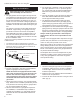
RDVN Series Direct Vent Gas Fireplace Model 33RDVN 33RDVP 36RDVN 36RDVP 39RDVN 39RDVP Model 33RDVN 33RDVP 36RDVN 36RDVP 39RDVN 39RDVP Normal and High Direct Vent Units - Inputs - Orifice Size - Altitude BTU/Hr BTU/Hr Manifold Pressure Orifice 0 - 2000ft. Altitude in USA Min. Input Max. Input @ Max. Orifice 0-4500ft Altitude in Canada 13,000 18,000 3.5”w.c. #47 DMS 13,000 18,000 10.0” w.c. #56 DMS 13,000 20,000 3.5” w.c. #45 DMS 13,000 20,000 10.0” w.c. #55 DMS 15,000 22,000 3.5” w.c.
RDVN Series Direct Vent Gas Fireplace 33RDVN Logs 1 1e 36/39RDVN Logs 1 1f 4a 1a 1b 1b 4b 1c 1a 1d 3 2 12 14 13 7 11 16a 21 19 16c 26 16b 27 18 28 29 34 30 31 CFM Corporation reserves the right to make changes in design, materials, specifications, prices and discontinue colors and products at any time, without notice. RDVN Series Gas Fireplace Units: GF1AR1, GF1AR2, GF1AR3 Ref. 1. 1a. 1b. 1c. 1d. 1e. 1f. 2.
RDVN Series Direct Vent Gas Fireplace RDVN Series Gas Fireplace Heater (continued) Ref. 3. 4a. 4b. 5. 6. 7a. 8a. 8b. 9. 10. 11. 12. 13. 14. 15. 16. 16b. 16c. 17. 18. 19. 20. 21. 22. 23. 24. 25. 26. 27. 28. 29. 30. 31. 32. 33. 34. Description Embers, Platinum Burner Tube Burner Tube Orifice, Burner, Nat. (not shown) Orifice, Burner, LP (not shown) Pilot Assembly, SIT Top Convertible - Nat. Pilot Orifice - LP Pilot Orifice - Nat. Rep. Reg. Assembly - LP, HI/LOW 82979 (not shown) Rep. Reg. Assembly - Nat.
RDVN Series Direct Vent Gas Fireplace Optional Accessories Fan Kits Thermal Sensor Fan FK24 Fan Assembly This auxiliary fan system increases the efficiency of the circulation of the heating air. The FK24 fan kit allows variable speed control of the circulation fan and also incorporates a heat sensor in the circuit. Specifications 115 Volt / 60Hz / 56 Watts Maintenance The fan itself does not require regular maintenance, however periodic cleaning of the fan and the surrounding area is required.
RDVN Series Direct Vent Gas Fireplace Wiring Instructions The fireplace, when installed, must be electrically connected and grounded in accordance with local codes or, in the absence of local codes, with the current CSA C22.1 Canadian Electric Code. For USA installations follow the local codes and the national electrical code ANSI/NFPA No. 70. Should this fan require servicing or repair the power supply must be disconnected. For rewiring of any replacement parts refer to Figure 59.
RDVN Series Direct Vent Gas Fireplace Top Louvre Bay Window Frame Ceramic Refractory Ceramic Refractory Bottom Louvre Assemblies Bottom Brass Trim CFM178 Screws FP1234 Fig. 61 Bay window installation. Bay Window Screen FP1234 Bay Window Screen Kits are available for the 33RDVN, 36RDVN & 39RDVN modelBay appliances. window 11/02 window frame Do not remove existing assembly! Remove all plastic from brass trims. Fig. 62 Bay window screen assembly.
RDVN Series Direct Vent Gas Fireplace 20007628 41
RDVN Series Direct Vent Gas Fireplace 42 20007628
RDVN Series Direct Vent Gas Fireplace 20007628 43
RDVN Series Direct Vent Gas Fireplace Limited Warranty TEMCO Fireplace Products Direct Vent Gas Fireplaces This warranty is limited to CFM Fireplace Products Direct Vent Gas Fireplaces (henceforth, Product) manufactured by CFM Corporation (henceforth, CFM). approval for warranty repair or replacement and to affect a warranty claim. The Checklist is found on Pages 41 and 42 of this manual.
RDVN Series Direct Vent Gas Fireplace TEMCO FIREPLACE PRODUCTS DIRECT VENT FIREPLACES INSTALLATION AND STARTUP CHECKLIST Customer Copy NOTE: TEMCO Fireplace Products gas logs and fireplaces require installation by a qualified gas appliance installer. A copy of this checklist must be submitted, along with proof of purchase, when applying to Technical Services for prior written approval of warranty repair or replacement. ❑ Read and understand installation instructions before attempting installation.
RDVN Series Direct Vent Gas Fireplace TEMCO FIREPLACE PRODUCTS DIRECT VENT FIREPLACES INSTALLATION AND STARTUP CHECKLIST Installer’s Copy NOTE: TEMCO Fireplace Products gas logs and fireplaces require installation by a qualified gas appliance installer. A copy of this checklist must be submitted, along with proof of purchase, when applying to Technical Services for prior written approval of warranty repair or replacement. ❑ Read and understand installation instructions before installing.
RDVN Series Direct Vent Gas Fireplace Customer Copy Model # ______________________________________ Serial # ______________________________________ I certify that I have followed all codes and regulations and adhered to the TEMCO Fireplace Products installation instructions. I have completed the proper installation and startup checklist.
Efficiency Ratings Model 33RDVN 33RDVP 36RDVN 36RDVP 39RDVN 39RDVP EnerGuide Ratings Fireplace Efficiency (%) 48.4 48.4 48.9 48.9 56.5 56.5 CFM Corporation 2695 Meadowvale Blvd. • Mississauga, Ontario, Canada L5N 8A3 800-668-5323 • www.cfmcorp.