INSTALLER/CONSUMER SAFETY INFORMATION PLEASE READ THIS MANUAL BEFORE INSTALLING AND USING APPLIANCE WARNING! IF THE INFORMATION IN THIS MANUAL IS NOT FOLLOWED EXACTLY, A FIRE OR EXPLOSION MAY RESULT CAUSING PROPERTY DAMAGE, PERSONAL INJURY OR LOSS OF LIFE. Direct Vent Zero Clearance Gas Fireplace Heater Model: 41DVN, 41DVDSN FOR YOUR SAFETY Installation and service must be performed by a qualified installer, service agency or the gas supplier.
41DVN / DVSN Direct Vent Gas Fireplace Table of Contents PLEASE READ THE INSTALLATION & OPERATING INSTRUCTIONS BEFORE USING APPLIANCE. Thank you and congratulations on your purchase of a CFM Corporation fireplace. IMPORTANT: Read all instructions and warnings carefully before starting installation. Failure to follow these instructions may result in a possible fire hazard and will void the warranty.
41DVN / DVSN Direct Vent Gas Fireplace Installation & Operating Instructions This gas appliance should be installed by a qualified installer, preferably NFI or WETT (Canada) certified, in accordance with local building codes and with current CSA-B149.1 Installation codes for Gas Burning Appliances and Equipment. If the unit is being installed in a mobile home, the installation should comply with the current CAN/CSA Z 240.4 code. For U.S.
1DVN / DVSN Direct Vent Gas Fireplace Installation & Operating Instructions Requirements for the Commonwealth of Massachusetts All gas fitting and installation of this heater shall only be done by a licensed gas fitter or licensed plumber.
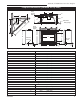
41DVN / DVSN Direct Vent Gas Fireplace Fireplace Dimensions (Installed as Top Vent) Rough Opening Depth V J P I T Q H V Nailing Flange K W K Recessed S - Rough Opening Width Rough Opening Height U G F R B D C Electrical Access Gas Line Access E L M A G N O Fig. 1 Fireplace specifications and framing dimensions. Ref.
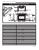
41DVN / DVSN Direct Vent Gas Fireplace Fireplace Dimensions (Installed as Rear Vent) Rough Opening Depth U I S H J Recessed U Nailing Flange J V R - Rough Opening Width Rough Opening Height T G F Q B Electrical Access P D C Gas Line Access O E K A L G H N Fig. 2 Fireplace specifications and framing dimensions. Ref.
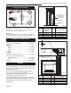
41DVN / DVSN Direct Vent Gas Fireplace Locating Your Fireplace V W X Y Y E Z A B C Y Maintain Minimum 3/4” (19 mm) Clearance to Combustibles X A B C D E Fireplace D Louvre Assembly Top B F Top of Combustion Chamber LU584-1 Fig. 3 Locating Gas Fireplace LU584-1 Locating unit C) **Island 2/4/99 djt A) Flat on wall B) Cross corner D) Room divider E) Flat on wall corner F) Chase installation Y) Refer to “Clearance to Combustibles” Section Note (Fig.
41DVN / DVSN Direct Vent Gas Fireplace Hearth Gas Specifications A hearth is not mandatory, but is recommended for aesthetic purposes. We recommend a noncombustible hearth which projects out 12” (305 mm) or more from the front of the fireplace. Cold climate installation recommendation: When installing this unit against a non-insulated exterior wall or chase, it is mandatory that the outer walls be insulated to conform to applicable insulation codes.
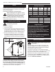
41DVN / DVSN Direct Vent Gas Fireplace 1/2” Gas Supply 1/2” NPT x 3/8” Flare Shut-off Valve 3/8” Flex Line (from valve) FP297a Fig. 6 Typical gas supply installation. Always check for gas leaks with a mild soap and water solution applied with a brush no larger FP297A than 1” (25 mm). Never INSTA VENT FREE apply soap and water solution with a spray UVHB26 GAS SUPPLY bottle. Do not use an open flame for leak 7/1/98 testing. The fireplace valve must not be subjected to any test pressures exceeding 1/2 psi.
41DVN / DVSN Direct Vent Gas Fireplace 2. Attach the wire to the ON/OFF switch and install switch into receptacle box. Attach cover plate to switch. 3. Connect wiring to gas valve. (Fig. 7) Remote ON/OFF Switch TPTH TP TH FP1218 Fig. 7 Remote switch wiring diagram for millivolt models. Alternate Switch Location The remote switch can be installed on either side of the access door. Mount the switch to the switch bracket provided.
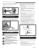
41DVN / DVSN Direct Vent Gas Fireplace 4. Remove the four (4) screws securing flue pipe to back of unit. Remove flue pipe. (Fig. 11) 5. Secure flue cover to back of flue outlet. Be sure to replace gasket. (Fig. 12) 6. Install flue pipe and gasket removed in step 4 to top of unit with four (4) screws. Be sure to replace gasket. (Fig. 12) 7. Secure outer collar adapter to unit with the round collar on top, secure with 10 screws. NOTE: Be sure not to damage any gasket material.
41DVN / DVSN Direct Vent Gas Fireplace General Venting Your fireplace is approved to be vented either through the side wall, or vertical through the roof. • Only CFM Corporation venting components specifically approved and labelled for this fireplace may be used. • Venting terminals shall not be recessed into a wall or siding. • Horizontal venting which incorporates the twist lock pipe must be installed on a level plane without an inclining or declining slope.
41DVN / DVSN Direct Vent Gas Fireplace General Venting Information - Termination Location INSIDE CORNER DETAIL G V H A N N D L V E C B V F B ����� ������ Ope B V Operable rable V B B B J X X AIR SUPPLY INLET M I A CFM145a V VENT TERMINATION V V Fixed Closed V K X AREA WHERE TERMINAL IS NOT PERMITTED Canadian Installations1 US Installations2 A = Clearance above grade, veranda, porch, deck, or balcony B = Clearance to window or door that may be opened 12” (30 cm) CFM145a
41DVN / DVSN Direct Vent Gas Fireplace Termination Clearances Termination clearances for buildings with combustible and noncombustible exteriors. Inside Corner Alcove Applications* Outside Corner G= Combustible 6" (152 mm) G F= Combustible 6" (152 mm) Noncombustible 2" (51 mm) V Noncombustible 2" (51 mm) V C V E O F Balcony with perpendicular side wall Balcony with no side wall D C E = Min. 6” (152 mm) for non-vinyl sidewalls Min. 12” (305 mm) for vinyl sidewalls O = 8’ (2.4 m) Min.
41DVN / DVSN Direct Vent Gas Fireplace Twist Lock Pipes When using twist lock pipe it is not necessary to use sealant on the joints. The only areas of the venting system that need to be sealed with high temperature silicone sealant are the collars on the fireplace and termination, and the sliding joint of any telescopic vent section used in the system.
41DVN / DVSN Direct Vent Gas Fireplace Vent Opening for Combustible Wall 9³⁄₈" (240 mm) 20” (508 mm) Max. Rear Vent Top View Framing Detail 10³⁄₈" (265 mm) Fireplace Hearth DVR584-600 Opening for Noncombustible Wall Fig. 19 Rear vent application, no elbows. DVR584-600 20" 20" Rear vent no elbows (508mm) (508mm) Max. Max. 2/99 djt 7¹⁄₂" Dia. (190 mm) Rnd. Fireplace Hearth VO584-100 Fig. 21 Locate vent opening on wall.
41DVN / DVSN Direct Vent Gas Fireplace Finished Wall 12" (305mm) Vent Termination 1/2" (13mm) NOTE: Minimum 1” (25mm) rise on any installation. FP1472 Fig. 25 There must be a 1/2” rise in 12” length. Vertical Sidewall Application FP1005 Fig. 23 Side view of final unit location. FP1005 Rear Wall Vent Installations View Vent Termination FlexSide Vent Pipe 1/25/00 djt Follow Steps 1 and 2 on Page 16.
41DVN / DVSN Direct Vent Gas Fireplace • The maximum number of 90° elbows per side wall installation is three (3). (Fig. 2) A • If a 90° elbow is fitted directly on top of the fireplace flange the maximum horizontal vent run before the termination or a vertical rise is 36” (914 mm). (Fig. 27) 3 x 90° Elbows 8’ (244 cm) 3 x 90° Elbows 7’ (178 cm) 10’ (254 cm) B A + B = 17’ (518cm) Max. V584-201 Fig. 29 Maximum vent run with elbows. V584-201 FP1176 Fig.
41DVN / DVSN Direct Vent Gas Fireplace Vertical Sidewall Installation Twist Lock Pipe Max. Length 12” (305mm) Adjustable Zero Clearance Sleeve Step 1 Locate vent opening on the wall. It may be necessary to first position the fireplace and measure to obtain hole location. Depending on whether the wall is combustible or noncombustible, cut opening to size. (Fig. 31) (For combustible walls first frame in opening.
41DVN / DVSN Direct Vent Gas Fireplace Sealing vent pipe and firestop gaps with high temperature sealant will restrict cold air being drawn in around fireplace. X installed spring. Place the next spring approximately 8” (203 mm) from the last spring. Finally place the last spring approximately 8” (203 mm) from the last spring installed. (Fig. 24) Maintain equal spacing between spacer springs. 4” Flex Vent Pipe X Spacer Spring 8" (203mm) 8" (203mm) 8" (203mm) 8" (203mm) FP1182 Fig.
41DVN / DVSN Direct Vent Gas Fireplace Below Grade Installation When it is not possible to meet the required vent terminal clearances of 12” (305 mm) above grade level, a snorkel kit is recommended. It allows installation depth down to 7” (178 mm) below grade level. The 7” (178 mm) is measured from the center of the horizontal vent pipe as it penetrates through the wall. Ensure the sidewall venting clearances are observed.
41DVN / DVSN Direct Vent Gas Fireplace Vertical Through-the-Roof Installation Max. Height 40’ (12.2m) Min. Height 8’ (2.4m) Max. 10’ (3m) Support Straps Every 3’ (.9m) Max. Height 40’ (12.2m) Min. Height 8’ (2.4m) Max. 10’ (3m) FP1183 Fig. 39 Support straps for horizontal runs. 1 + 2 + 3 + 4 = 270° 1 2 3 4 1. Locate your fireplace. 2. Plumb to center of the (4”) flue collar from ceiling above and mark position. 3. Cut opening equal to 9³⁄₈” x 9³⁄₈” (240 x 240 mm). 4.
41DVN / DVSN Direct Vent Gas Fireplace 3 #5 Sheet Metal Screws per Joint Sealant Storm Collar Typical Roof Support Application Typical Ceiling Support Application FP1184 Typical roof/ceiling support apps. TWL101a FP1184 Fig. 42 Venting supports. Fig. 44 Roof flashing. TWL101a Twist Lock Pipe 2/8/99 djt Min. 2' (610 mm) FP1185 Fig. 43 Minimum termination to roof clearance.
41DVN / DVSN Direct Vent Gas Fireplace Twist Lock Venting Components 7TDVRVT - Through the wall Rear Vent Termination 584A venting components rear vent term 4/6/99 djt Starter Kit Model 7TDVSK - Sidewall Venting (Twist Lock Pipe) Model 7FDVSK - Sidewall Venting (Flex Vent Pipe) Starter Kit - Model 7TDVSKV - Vertical Venting for 7TDVSKV-A order 1/12 to 6/12 roof pitch for 7TDVSKV-B order 7/12 to 12/12 roof pitch for 7TDVSKV-F order flat roof Starter Kit for Below Grade Installation Model 7TDVSKS -Snorkel K
41DVN / DVSN Direct Vent Gas Fireplace Operating Instructions Glass Information Window Frame Assembly Only glass approved by CFM Corporation should be used on this fireplace. Fireplace Front • The use of any non-approved replacement glass will void all product warranties. • Care must be taken to avoid breakage of the glass. • Do not operate appliance with glass front • removed, cracked or broken.
41DVN / DVSN Direct Vent Gas Fireplace Installation of Logs, Lava Rock and Ember Material Unpack the logs from packaging and remove each log from its wrapping materials. The logs are fragile and should be handled with care. Keep the packaging material out of the reach of children and dispose of the material in a safe manner. The embers supplied with your fireplace are made from a high grade rock wool and should be handled carefully. Wash your hands immediately after touching to avoid irritation.
41DVN / DVSN Direct Vent Gas Fireplace Flame Characteristics Twig Back Log It is important to periodically perform a visual check of the pilot and the burner flames. Pilot flame is shown in Figure 51. If the flames appear abnormal call a service person. Front Log Slot Bracket Bracket TL122 Fig. 49 Side view of logset.
41DVN / DVSN Direct Vent Gas Fireplace Lighting and Operating Instructions - Millivolt Models FOR YOUR SAFETY READ BEFORE LIGHTING WARNING:If you do not follow these instructions exactly, a fire or explosion may result causing property damage, personal injury or loss of life. A. This heater has a pilot which must be lit manually. When lighting the pilot follow these instructions exactly. B. BEFORE LIGHTING smell all around the heater area for gas.
41DVN / DVSN Direct Vent Gas Fireplace Lighting and Operating Instructions - Direct Spark Models FOR YOUR SAFETY READ BEFORE LIGHTING WARNING:If you do not follow these instructions exactly, a fire or explosion may result causing property damage, personal injury or loss of life. A. This heater has a pilot which must be lit manually. When lighting the pilot follow these instructions exactly. B. BEFORE LIGHTING smell all around the heater area for gas.
41DVN / DVSN Direct Vent Gas Fireplace Troubleshooting SIT Millivolt Valve NOTE: Before troubleshooting the gas control system, be sure external shut off is in the “ON” position. WARNING: Before doing any gas control service work, remove glass front! Table 1 Valve Type NOVA MV Plus Main Operator Minimum Voltage 145mV Coil Resistance 2.25Ω ± 0.5Ω Safety Magnet Hold-in Current Less than 285mA Drop-out Current Greater than 125mA Coil Resistance 0.108Ω ± 0.003Ω System Checks Problem Pilot will not light.
41DVN / DVSN Direct Vent Gas Fireplace System Checks (continued) Problem Possible Cause Defective thermo-generator. (Millivolt system) Defective safety magnet. (mV Plus systems) Defective Safety Magnet (Millivolt system) Pilot drops out. Pilot orifice blocked. type. Wrong pilot orifice. No gas to main burner Low gas pressure to appliance. Pilot not lit. Control knob not in ON Thermostat/wall switch will not cycle main burner. 20009999 Thermostat not in ON position.
41DVN / DVSN Direct Vent Gas Fireplace System Checks (continued) Problem Possible Cause Solution Thermo-generator output voltage not within design parameters. After the pilot has been lit for approximately three minutes, and only the thermo-generator wire connected to the main operator head, measure the voltage across TPTH and TP. This open circuit voltage should be between 500mV and 750mV. Tune the pilot adjustment screw until the mV reading falls within these parameters.
41DVN / DVSN Direct Vent Gas Fireplace Troubleshooting - Direct Spark Models NOTE: Before troubleshooting the gas control system, be sure external shut off is in the “ON” position. WARNING: Before doing any gas control service work, remove glass front! Problem No gas to main burner Possible Cause Low gas pressure to the appliance. Thermostat/wall switch Gas line valve not in ON position. Thermostat not in ON position. Thermostat/wall switch Defective thermostat or thermostat wiring.
41DVN / DVSN Direct Vent Gas Fireplace Fuel Conversion Instructions - 41DVN Left Flame Shield Burner Shield WARNING: This HI/LO conversion kit must ONLY be applied as part of a conversion kit supplied by the appliance manufacturer for the specific appliance and type of gas being converted. The conversion shall be carried out in accordance with the requirements of the provincial authorities having jurisdiction and in accordance with the requirements of the CSA B149.
41DVN / DVSN Direct Vent Gas Fireplace Replace Pilot Orifice LPG NG 1. The pilot hood is held in place by spring pressure. Remove the hood by pulling it directly up from the pilot bracket. (Fig. 54) 2. Insert a 3/32” (4mm) Allen wrench into the hexagonal keyway of the injector (Fig. 54) and rotate it counterclockwise until it is free of the injector journal. (Fig. 54) T208 Fig. 55 Injectors. ConvertT208 Valve to LP conversion 1.
41DVN / DVSN Direct Vent Gas Fireplace Pressure ranges are: A Gas Supply Pressure (inches w.c.) Minimum Normal Maximum LP (Propane) 10.8 11.0 14.0 Manifold Pressure (inches w.c.) Normal (HI) Normal (Low) LP (Propane) 10.0” 6.3” B Manifold pressure can be measured by using a 5/16” I.D. hose in the right hand side of the valve and connecting a manometer. Two test gauge ports are accessible for test gauge connection: C 1. Tap on left side of the valve will give inlet supply pressure. 2.
41DVN / DVSN Direct Vent Gas Fireplace Fuel Conversion Instructions - 41DVDSN Left Flame Shield Burner Shield The conversion shall be carried out in accordance with the requirements of the provincial authorities having jurisdiction and in accordance with the requirements of the CSA B149.2 installation Code (Canada) and with the requirements of the National Fuel Gas Code Z223.1/NFPA 54 (United States).
41DVN / DVSN Direct Vent Gas Fireplace A 1 2 Regulator Fitting 3 4 Air Shutter Settings Model Opening A 41DVDSP Fully Open T210 Fig. 60 White-Rodgers 25M18A-706PI gas control. 2. Loosen screw and attach a manometer or pressure gauge to the outlet pressure tap of the control valve. 3. Turn on the gas supply. Turn on the electrical supply T210for gas leaks using soap and to the appliance. Check water solution or leakWhite-rodgers detection solution.
41DVN / DVSN Direct Vent Gas Fireplace Unit Adjustment - 41DVN / 41DVP Once installed, the unit should be operated at least three (3) times to ensure that all is in working order. NOTE: Manufacturing oils will smoke during initial firing of appliance. Open windows for ventilation.
41DVN / DVSN Direct Vent Gas Fireplace Unit Adjustment - 41DVDSN / 41DVDSP Once installed, the unit should be operated at least three (3) times to ensure that all is in working order. NOTE: Manufacturing oils will smoke during initial firing of appliance. Open windows for ventilation.
DVN / DVSN Direct Vent Gas Fireplace Maintenance Burner and Burner Compartment 1. Turn off pilot light at gas valve side. It is important to keep the burner and the burner compartment clean. At least once per year the logs and lava rock/ember material should be removed and the burner compartment vacuumed and wiped out. Remove and replace the logs as per the instructions in this manual. Always handle the logs with care as they are fragile and may also be hot if the fireplace has been in use.
41DVN / DVSN Direct Vent Gas Fireplace Model 41DVN 41DVP 41DVDSN 41DVDSP Normal and High Direct Vent Units - Inputs - Orifice Size - Altitude BTU/Hr BTU/Hr Manifold Pressure Orifice 0 - 2000ft. Altitude in USA Min. Input Max. Input @ Max. Orifice 0-4500ft Altitude in Canada 20,000 30,000 3.5”w.c. #37 DMS 19,000 27,000 10.0” w.c. #53 -30,000 3.5” w.c. #37 DMS -27,000 10.0” w.c.
41DVN / DVSN Direct Vent Gas Fireplace 1 5 2 4 1d 3 1b 1a 6a 7 6b 1c 19 8a 8c 8b 20 21 1 2 30 29 21 11 26 10 9 13 31 23a,b 3 4 36 14 35 12 44 43 32 48 33 40 34 41 46 45 42 47 CFM Corporation reserves the right to make changes in design, materials, specifications, prices and discontinue colors and products at any time, without notice.
41DVN / DVSN Direct Vent Gas Fireplace 41DVN / 41DVDSN Series Gas Fireplace (continued) Ref. 1. 1a. 1b. 1c. 1d. 2. 3. 4. 5. 6a. 6b. 7. 8a. 8b. 8c. 9. 10. 11. 12. 13. 14. 15. 16. 17. 18. 19. 20a. 20b. 21. 22a. 22b. 23. 24. 25. 26. 27. 28. 29. 30. 31. 32. 33. 34. 35. 36. 37. 38. 44 Description Log Set 41DV (Complete) Log Rear Log Right Twig Log Left Twig Log Front Volcanic Rock Package (1lb.
41DVN / DVSN Direct Vent Gas Fireplace 41DVN / 41DVDSN Series Gas Fireplace (continued) Ref. 39. 40. 41. 42. 43. 44. 45. 46. 47. 48. Description Wire Harness (not shown) Firestop Zero Clearance Sleeve Plate Cover Air Inlet w/7” Collar Assy. Gasket Plate Air Inlet Plate Cover Flue Products Gasket Plate Cover Flue Products Plate Flue Pipe Assy.
41DVN / DVSN Direct Vent Gas Fireplace Optional Accessories Available Fan Kits FK12 Fan Assembly 1. Open louvre assembly bottom. 2. Install FK12 fan in back of unit between hearth supports. (Fig. 62) 3. Secure fan on velcro strips. 4. Power to the fan can be supplied by plugging the supply lead into a conveniently located wall socket or by using a hard-wired EB-1 connector box. 5. Be sure fan motor does not touch hearth supports. Cold Air Box Front of Unit Hard (Direct) Wire Hook Up Fig.
41DVN / DVSN Direct Vent Gas Fireplace Decorative Bay Windows Remote ON/OFF Switch The optional ON/OFF Switch Kit (53875) allows the fireplace to be turned on or off from a remotely located wall switch. Installation instructions begin on Page 8. Remote Controls Installation Remove the existing louvre assembly top. Assemble the Bay Window Kit according to the instructions supplied with the kit. (Fig. 66) Optional remote control units are available to control different functions of the appliance.
41DVN / DVSN Direct Vent Gas Fireplace Limited Warranty TEMCO Fireplace Products Direct Vent Gas Fireplaces This warranty is limited to CFM Fireplace Products Direct Vent Gas Fireplaces (henceforth, Product) manufactured by CFM Corporation (henceforth, CFM). prior approval for warranty repair or replacement and to affect a warranty claim. The Checklist is found on Pages 49 and 50 of this manual.
41DVN / DVSN Direct Vent Gas Fireplace TEMCO FIREPLACE PRODUCTS DIRECT VENT FIREPLACES INSTALLATION AND STARTUP CHECKLIST Customer Copy NOTE: TEMCO Fireplace Products gas logs and fireplaces require installation by a qualified gas appliance installer. A copy of this checklist must be submitted, along with proof of purchase, when applying to Technical Services for prior written approval of warranty repair or replacement. ❑ Read and understand installation instructions before attempting installation.
41DVN / DVSN Direct Vent Gas Fireplace TEMCO FIREPLACE PRODUCTS DIRECT VENT FIREPLACES INSTALLATION AND STARTUP CHECKLIST Installer’s Copy NOTE: TEMCO Fireplace Products gas logs and fireplaces require installation by a qualified gas appliance installer. A copy of this checklist must be submitted, along with proof of purchase, when applying to Technical Services for prior written approval of warranty repair or replacement. ❑ Read and understand installation instructions before installing.
41DVN / DVSN Direct Vent Gas Fireplace Customer Copy Model # ______________________________________ Serial # ______________________________________ I certify that I have followed all codes and regulations and adhered to the TEMCO Fireplace Products installation instructions. I have completed the proper installation and startup checklist.
Efficiency Ratings Model 41DVN 41DVP 41DVDSN 41DVDSP EnerGuide Ratings Fireplace Efficiency (%) 53 53 64.7 64.7 CFM Corporation 2695 Meadowvale Blvd. • Mississauga, Ontario, Canada L5N 8A3 800-668-5323 • www.cfmcorp.