3640 (Electric) Sweeper English EN Operator Manual 330569 Rev. 08 (02-2008) *330569* www.tennantco.com Home Find... Go To..
This manual is furnished with each new model. It provides necessary operation and maintenance instructions. Read this manual completely and understand the machine before operating or servicing it. This machine will provide excellent service. However, the best results will be obtained at minimum costs if: S The machine is operated with reasonable care. S The machine is maintained regularly - per the machine maintenance instructions provided.
CONTENTS CONTENTS Page SAFETY PRECAUTIONS . . . . . . . . . . . . . . . . . 3 OPERATION . . . . . . . . . . . . . . . . . . . . . . . . . . . . 5 OPERATOR RESPONSIBILITY . . . . . . . . . 5 MACHINE COMPONENTS . . . . . . . . . . . . . 6 SYMBOL DEFINITIONS . . . . . . . . . . . . . . . . 7 CONTROLS AND INSTRUMENTS . . . . . . 8 OPERATION OF CONTROLS . . . . . . . . . . 9 DIRECTIONAL CONTROL LEVER . . . 9 CLUTCH HANDLE . . . . . . . . . . . . . . . . . . 11 MAIN BRUSH LEVER . . . . . . . . . . . . . . .
CONTENTS 2 3640E 330569 (2--01) Home Find... Go To..
SAFETY PRECAUTIONS SAFETY PRECAUTIONS The following symbols are used throughout this manual as indicated in their description: WARNING: To warn of hazards or unsafe practices that could result in severe personal injury or death. FOR SAFETY: To identify actions that must be followed for safe operation of equipment. The machine is suited to sweep disposable debris. Do not use the machine other than described in this Operator Manual. The machine is not designed for use on public roads.
SAFETY PRECAUTIONS The following safety labels are mounted on the machine in the locations indicated. If these or any labels become damaged or illegible, install a new label in its place. BATTERY CHARGING LABEL -LOCATED ON THE UNDERSIDE OF THE BATTERY COMPARTMENT COVER FOR SAFETY LABEL -- LOCATED ON THE CONTROL PANEL BACK STRAIN LABEL -- LOCATED ON THE MOTOR COMPARTMENT COVER FLYING DEBRIS WARNING LABEL -- LOCATED ON THE MOTOR COMPARTMENT COVER 350842 4 3640E 330569 (01--00) Home Find... Go To..
OPERATION OPERATION OPERATOR RESPONSIBILITY - The operator’s responsibility is to take care of the daily maintenance and checkups of the machine to keep it in good working condition. The operator must inform the service mechanic or supervisor when the maintenance intervals are required as stated in the MAINTENANCE section of this manual. - Read this manual carefully before operating the machine. View the operation video supplied with the machine.
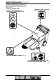
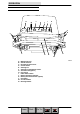
OPERATION MACHINE COMPONENTS G A F H C D E B A. B. C. D. E. F. G. H. Debris hopper Vacuum wand (option) Filter compartment Main brush Side brush Accessory bin Battery compartment Vac wand extension (option) 6 350660 3640E 330569 (01--00) Home Find... Go To..
OPERATION SYMBOL DEFINITIONS These symbols identify controls, displays, and features on the machine: Start Filter shaker switch Side brush(es) down and on Side brush(es) up and off Main brush down pressure Main brush down and on Main brush up and off Battery discharge indicator Circuit breaker #1 Circuit breaker #2 7 3640E 330569 (01--00) Home Find... Go To..
OPERATION CONTROLS AND INSTRUMENTS N M L K J I H A B C F E F D G A. B. C. D. E. F. G. H. I. J. K. L. M. N. Main brush lever Side brush lever Directional control lever Clutch handle Steering bar Steering bar adjustment knobs. Vacuum wand (option) Key switch Filter shaker switch Battery discharge indicator Battery disconnect button (option) Hourmeter Circuit breakers Beverage holder 8 350658 3640E 330569 (01--00) Home Find... Go To..
OPERATION OPERATION OF CONTROLS DIRECTIONAL CONTROL LEVER The directional control lever controls the machine’s speed and direction of travel. The machine has three forward speeds: second, first, and third; one reverse speed; as well as neutral and park settings. The speed selection pattern is designed to allow the operator to move the control lever quickly between second speed and reverse. The neutral setting is located midway between these positions.
OPERATION NEUTRAL: Push the directional control lever halfway between the REVERSE position and the SECOND SPEED position. The machine will not move forward when the clutch handle is squeezed while in NEUTRAL. Do not leave the machine powered on in NEUTRAL while the machine is unattended. SECOND SPEED: Push the directional control lever one position forward from the NEUTRAL position. The machine will move forward when the clutch handle is squeezed. Use SECOND SPEED for normal sweeping.
OPERATION CLUTCH HANDLE The clutch handle engages the machine’s propelling system when the direction control lever is positioned in a forward or reverse position. The farther the clutch handle is squeezed toward the steering bar, the faster the machine will travel, up to its maximum in the selected position. Braking: To stop the machine at any time, regardless of direction of travel, release the clutch handle. The machine will immediately slow down, then stop completely.
OPERATION SIDE BRUSH LEVER The side brush lever raises and lowers the side brush. The side brush will rotate automatically when lowered. The side brush does not rotate when raised. Side brush down and on: Move the side brush lever to the right, out the the raised position, then forward to the desired brush down pressure setting. Side brush up and off: Move the side brush lever backward, then to the left to raise and set the side brush in the raised position.
OPERATION KEY SWITCH The ignition switch turns the power to the machine on and off using a key. On: Turn the key clockwise as far as it will go and release it to the on position. Off: Turn the key counterclockwise. HOURMETER The hourmeter records the number of hours the machine has been in use. Use this information as a guide to indicate when routine maintenance needs to be performed.
OPERATION POWER KILL SWITCH (OPTION) The Power Kill Switch immediately stops all power to the machine. Stop machine power: Press the Power Kill Switch. Restart machine power: Release the Power Kill Switch by turning it to the right. Turn the key counter--clockwise, then turn the key fully clockwise and release it to the on position. CIRCUIT BREAKERS Circuit breakers are resetable electrical circuit protection devices designed to stop the flow of current in the event of a circuit overload.
OPERATION FILTER SHAKER SWITCH The filter shaker switch activates the filter shaker motor. The shaker motor shakes debris from the panel filter. Machines with a bag filter do not have a filter shaker motor or switch. Make sure the filter compartment door is closed properly, then press the switch. The filter shaker motor will shake the filter for 15 seconds, then stop automatically. Remove loose debris from the panel filter compartment door when the shaker motor stops.
OPERATION HOW THE MACHINE WORKS The operator steers the machine by using the steering bar. The directional control lever controls the forward or reverse direction of the machine. The clutch handle engages the propelling system when it is squeezed toward the steering bar. The clutch handle will also stop the machine when it is released. The side brush sweeps debris into the path of the main brush. The main brush sweeps debris from the floor into the hopper.
OPERATION STARTING THE MACHINE 1. Turn the machine power on. 2. Move the directional control lever into the desired forward speed (second, first, or third). 3. Gently squeeze the clutch handle to move the machine forward. NOTE: The farther the clutch handle is squeezed toward the steering bar, the faster the machine will travel, up to its maximum in the selected position. 4. Drive the machine to the area to be swept. 17 3640E 330569 (01--00) Home Find... Go To..
OPERATION SWEEPING AND BRUSH INFORMATION Pick up oversized debris before sweeping. Flatten or remove bulky cartons from aisles before sweeping. Pick up pieces of wire, twine, string, etc., which could become entangled in the brushes or brush plugs. Plan the sweeping in advance. Try to arrange long runs with minimum stopping and starting. Sweep debris from very narrow aisles into the main aisles ahead of time. Do an entire floor or section at one time. Drive the straightest path possible.
OPERATION SWEEPING 1. Drive the machine to the area to be swept. 2. Release the clutch handle to stop the machine. 3. Move the main brush lever to the left, out of the raised position, then allow it to fall forward into the sweeping position. 4. Move the side brush lever to the right, out of the raised position, then forward to the desired brush down pressure setting. 5. Squeeze the clutch handle to begin sweeping. 6. Sweep as needed. 19 3640E 330569 (01--00) Home Find... Go To..
OPERATION SWEEPING CARPET 1. If necessary, remove the floor sweeping brush and install the carpet sweeping brush. NOTE: DO NOT attempt to sweep carpet with a floor sweeping brush. Damage to the carpet could result. 2. Clean the rear wheels and front casters with a damp cloth before sweeping carpet. 3. Install the carpet sweeping pin into the main brush lever to control carpet brush down pressure. Do not attempt to sweep carpet without first installing the brush down pressure pin. 4.
OPERATION STOP SWEEPING 1. Release the clutch handle. NOTE: The machine will immediately slow down, then stop completely. 2. Move the main brush lever backward, then to the right to raise and set the main brush in the raised position. 3. Move the side brush lever backward, then to the left to raise and set the side brush(es) in the raised position. 21 3640E 330569 (01--00) Home Find... Go To..
OPERATION 4. Move the directional control lever into the PARK position. 5. Shake the panel filter by pressing the filter shaker switch. The shaker motor will operate for 15 seconds before stopping. NOTE: Make sure the filter compartment is closed securely before activating filter shaker. 6. Turn the machine power off. 22 3640E 330569 (01--00) Home Find... Go To..
OPERATION EMPTYING THE DEBRIS HOPPER STANDARD HOPPER Drive the machine to the area where debris is collected. Turn the machine power off. WARNING: Brush throws debris. Stop motor before lifting hopper. The debris hopper is equipped with one center, and two side finger grips to allow two people to lift and empty the hopper. Pull the hopper slightly forward to unseat it from the machine frame. With one person on each side, lift the debris hopper out of the machine.
OPERATION HOPPER DUMP ASSIST HANDLE (OPTION) The dump assist handle allows easy removal and transport of the debris hopper when it is full. Turn the machine power off. WARNING: Brush throws debris. Stop motor before lifting hopper. Raise the dump assist handle. Place one foot on the hopper’s pivot point. Lift the hopper out of the machine and onto the wheels. Transport the hopper to the location where debris is collected. WARNING: Heavy hopper. Get help to handle.
OPERATION REPLACING THE BAG FILTER (OPTION) The bag filter (options) traps dust and small particles of debris. Check the bag filter daily and replace it when it becomes full of debris. To access the bag filter, remove the vacuum wand and unlatch the filter compartment hooks. Install a new bag filter by placing the cardboard tab on the filter around the vacuum inlet tube. The vacuum inlet tube is located at the top of filter compartment, on the inside of the machine. Latch the filter compartment door.
OPERATION CLEANING THE FILTER COMPARTMENT The panel filter traps dust and small particles of debris. Press the filter shaker switch to shake the debris from the panel filter each time the hopper is emptied. This debris collects in the filter compartment. Clean the filter compartment daily. Remove the vacuum wand and unlatch the filter compartment hooks. Lower and remove the filter compartment door by sliding it to the left off the pivot pins. Empty the dust and debris.
OPERATION POST-OPERATION CHECKLIST Check this list of items after sweeping and emptying hopper: - Check for wire or string tangled in the bristles of the main brush and side brush(es). Additional side brush (option) shown. FOR SAFETY: Before leaving or servicing machine, stop on level surface, turn off machine, and remove key. - Check and, if necessary, wipe the vacuum inlet plate clean. - Check the skirts and seals for damage and wear. - Check the electrolyte levels in the battery cells after charging.
OPERATION OPTIONS WIDE TRACK TIRES AND HEAVY DUTY CASTERS Wide track tires and heavy duty casters provide increased maneuverability and control on rough surfaces. 28 3640E 330569 (01--00) Home Find... Go To..
OPERATION MACHINE TROUBLESHOOTING Problem Cause Remedy Excessive dusting Vacuum hose clogged Unscrew hose from vac wand handle and clean Brush skirts and dust seals worn or damaged Replace brush skirts or dust seals Filter bag full or panel filter clogged Shake and / or clean or replace bag or panel filter Vacuum wand hose damaged Replace vacuum wand hose Vacuum wand not fully inserted into machine Insert fully Vacuum inlet plate clogged Remove / clean plate.
OPERATION 30 3640E 330569 (2--01) Home Find... Go To..
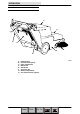
MAINTENANCE MAINTENANCE 1 2 6 3 4 5 7 8 350842 MAINTENANCE CHART Interval Daily Key Description 1 Battery cells 4,5 50 Hours 100 Hours 200 Hours 500 Hours 1000 Hours 2 2 6 6 Main brush and side brush(es) Vacuum inlet plate Skirts and seals Bag filter (option) Panel filter 1 5 Vacuum fan belt Main brush 1 6 7 8 Battery cells Panel filter (option) Wide track tires (option) Heavy duty casters (option) Battery terminals Side brush motor(s) Main motor 1 3 1 Procedure Check electrolyte level
MAINTENANCE BATTERIES The batteries are designed to hold their power for long periods of time. The lifetime of the batteries is limited to number of charges the batteries receive. To get the most life from the batteries, recharge them immediately when the battery discharge indicator begins to blink. Every 200 hours of operation, check for loose battery connections and clean the surface of the batteries, including terminals and cable clamps, using a strong solution of baking soda and water.
MAINTENANCE Using a hydrometer, measure the specific gravity to determine the charge level and condition of the batteries. If one or more of the battery cells test lower than the other battery cells (0.050 or more), the cell is damaged, shorted, or is near failure. Completely recharge the batteries, then retest them. NOTE: Do not take readings immediately after adding distilled water. If the water and acid are not thoroughly mixed, the readings may not be accurate.
MAINTENANCE 5. Check the electrolyte level in all the battery cells. 08247 6. If the level is low, add just enough distilled water to cover the plates. DO NOT OVERFILL. The batteries can overflow during charging due to expansion. NOTE: Make sure the battery caps are in place while charging. FOR SAFETY: When maintaining or servicing machine, avoid contact with battery acid. 7. Unplug the machine connector from the batteries. 8. Plug the charger connector into the battery connector.
MAINTENANCE 9. Plug the battery charger into the wall outlet. NOTE: If the red “ABNORMAL CYCLE” lamp lights when the TENNANT charger is plugged into a wall outlet, the charger cannot charge the battery and there is something wrong with the battery. 10.The TENNANT charger will start automatically. When the batteries are fully charged, the TENNANT charger will automatically turn off. 11. After the charger has turned off, unplug the charger from the wall outlet. 07224 12.
MAINTENANCE SKIRTS AND SEALS MAIN BRUSH SKIRTS The main brush skirts are located at the ends of the main brush. These skirts are designed to deflect debris into the hopper. Check the brush skirts for damage or wear daily. HOPPER DUST SEAL The hopper dust seal, located at the top of the hopper compartment, helps maintain a vacuum within the hopper. Check the hopper dust seal for damage or wear daily. REAR SKIRT The rear skirt, located behind the main brush, helps create a vacuum around the main brush.
MAINTENANCE HOPPER LIP SKIRT The hopper lip skirt, located on the lip of the hopper, ensures debris thrown from the main brush will go into the hopper. Check the hopper lip skirt for damage or wear daily. FILTER COMPARTMENT DOOR SEAL The filter door seal, located around the perimeter of the filter compartment door, helps maintain a vacuum around the filter. Check the filter compartment door seal for damage or wear daily.
MAINTENANCE CLEANING THE PANEL FILTER The panel filter filters the air pulled up from the hopper. The panel filter is equipped with a shaker to remove the accumulated dust particles. Remove and thoroughly clean the panel filter after every 100 hours of use. To remove the panel filter, unlatch and lower the filter compartment door. Unlatch the panel filter retainer and remove the filter.
MAINTENANCE BRUSHES MAIN BRUSH NOTE: The following procedures apply to both the floor sweeping main brush and the carpet sweeping main brush. The main brush spans the width of the machine and throws debris into the hopper. Check the brush for damage and wear daily. Remove string or wire tangled in the main brush or the main brush hub. Check the main brush pattern after every 50 hours of use. Adjust the main brush pattern by loosening the nut at the left end of the brush arm crossbar.
MAINTENANCE 3. Remove the debris hopper. 4. Pull the string guard and skirt back to avoid damaging. 5. Pull the main brush out of the machine through the hopper opening. 6. Remove the brush hub from the worn brush and install it into the new brush. 7. Install the new main brush into the machine. 8. Insert the main brush pin through the hole in the frame and into the main brush hub. Turn the main brush pin 1/4 turn clockwise. 9. Replace the hopper. 40 3640E 330569 (01--00) Home Find... Go To..
MAINTENANCE CHECKING AND ADJUSTING MAIN BRUSH PATTERN 1. Apply chalk (or another material that will not easily blow away), to a smooth, level section of the floor. 2. Lower the main brush in the chalked area. Allow the machine to sweep in the same place for 15 to 20 seconds. NOTE: If chalk or other material is not available, allow the brush to spin on the floor for two minutes. A polish mark will remain on the floor. 3. Raise the main brush and move the machine away from the chalked area.
MAINTENANCE ROTATING THE MAIN BRUSH 1. Turn the machine power off and move the directional lever into the PARK position. FOR SAFETY: Before leaving or servicing machine, stop on level surface, turn off machine, and remove key. 2. Turn the main brush pin 1/4 turn counter--clockwise and remove. 3. Remove the debris hopper. 4. Pull the main brush out of the machine through the hopper opening. 5. Remove the brush hub from the main brush and install it into the other end. 6.
MAINTENANCE SIDE BRUSH(ES) The side brush(es) sweep debris along walls and edges into the path of the main brush. Check the side brush(es) for damage and wear daily. Remove string or wire tangled in the side brush(es). A side brush should be replaced when it no longer effectively sweeps for your application. REPLACING THE SIDE BRUSH(ES) 1. Turn the machine power off and move the directional lever into the PARK position.
MAINTENANCE BELTS AND CHAINS VACUUM FAN BELT The vacuum fan belt drives the vacuum system. Check the belt for wear and tension after every 50 hours of operation. Check belt tension by applying a force 1 kg (2 lb) at belt midpoint. The proper deflection should be 5 mm (0.09 in). WARNING: Moving belt and fan. Keep away. MAIN BRUSH BELT The main brush drive belt is located behind the right rear tire. The belt drives the main brush. The proper belt tension is automatically set by a spring--loaded idler.
MAINTENANCE TIRES (OPTION) The heavy duty rear tires are pneumatic. Check the rear tires after every 100 hours of operation for damage. Check the rear tire pressure after every 100 hours of operation. The proper tire pressure is 345 kPa (50 psi). 45 3640E 330569 (01--00) Home Find... Go To..
MAINTENANCE PUSHING AND TRANSPORTING THE MACHINE PUSHING THE MACHINE If the machine becomes disabled, it can be easily pushed in neutral if necessary. TRANSPORTING THE MACHINE 1. Position the front of the machine at the loading edge of the truck or trailer. FOR SAFETY: Use truck or trailer that will support the weight of the machine. NOTE: Empty the hopper before transporting the machine. 2.
MAINTENANCE 5. Block the machine tires and place the directional control lever in Park. Tie down the machine to the truck or trailer before transporting. Secure the rear of the machine by wrapping straps around each end of the the handle and fastening them to the truck or trailer. Secure the front of the machine by wrapping a strap around the hopper and fastening it to the truck or trailer. 6.
MAINTENANCE STORING MACHINE When storing the machine for extended periods of time, the following procedures must be followed: 1. Raise the main and side brush(es). 2. Empty and clean the debris hopper. 3. Fully charge the batteries. 4. Disconnect the machine connector from the battery connector. 5. Store the machine in a clean dry area. 48 3640E 330569 (2--01) Home Find... Go To..
SPECIFICATIONS SPECIFICATIONS GENERAL MACHINE DIMENSIONS/CAPACITIES Item Dimension/capacity Length (Low / High steering bar position) 1428 / 1475 mm Width 820 mm Width (Wide track Wheels Kit Option) 933 mm Height (Low / High steering bar position) 881 / 960 mm GVWR -- 130 AH batteries 235 kg GVWR -- 215 AH batteries 281 kg Track 775 mm Wheelbase 492 mm Main brush diameter 203 mm Main brush length 610 mm Side brush diameter 420 mm Sweeping path width, main brush only 610 mm Sweeping
SPECIFICATIONS POWER TYPE Type Quantity Volts Ah Rating Weight Batteries 2 12 130 @ 20 hr rate 30 kg 2 12 215 @ 20 hr rate 55 kg Type Use VDC / Amp Kw (hp) Electric Motors Side brush(es) (disk) 24 V / 2.4 A 0.075 kw (0.1 hp) Main motor 24 V / 43 A 0.75 kw(1 hp) Type VDC Amp Hz Phase VAC Charger (Smart) 24 15 or 20 50 / 60 1 120 /240 TIRES Location Type Size Front (2) Casters 35 mm wide x 127 mm OD (1.
SPECIFICATIONS 820 mm 815 mm 1475 mm 960 mm MACHINE DIMENSIONS 51 3640E 330569 (2--01) Home Find... Go To..
SPECIFICATIONS 52 3640E 330569 (2--01) Home Find... Go To..