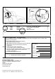
3640 (Electric) Sweeper Parts Manual TennantTrueR Parts For the latest Parts manuals and other language Operator manuals, visit: www.tennantco.com/manuals JP www.tennant.co.jp 330564 Rev.
B A Ref o Y 1 2 3 4 5 D6 Part No. Serial Number Description 82681 63810 51839 49263 82556 (000000) (000000) (000000) (000000) (000000- 001039 ) Bracket Wldt, Lpg Mount Latch Assy, Lpg Tank Mtg, W/Nut Nut Adjustable, Lpg Tank Mtg Tie, Cable Bracket, Vaporizer 1 4 2 3 1 54930 (000000- Vaporizer, LPG 1 C ) Qty. HOW TO ORDER PARTS - See diagram above Only use TENNANT Company supplied or equivalent parts. Parts and supplies may be ordered online, by phone, by fax or by mail.
JP o Y
STANDARD PARTS SECTION Contents 2 Page Fig. 1 - General Recommended Maintenance Items . . . . . . . . . . . . . . . . . . 2-2 Fig. 2 - Replacement Brushes . . . . . . . . . . . . . . . . . 2-3 Fig. 3 - Main Frame Group . . . . . . . . . . . . . . . . . . . 2-4 Fig. 4 - Drive System Group . . . . . . . . . . . . . . . . . . 2-6 Fig. 5 - Main Brush Group . . . . . . . . . . . . . . . . . . . . 2-8 Fig. 6 - Side Brush Group . . . . . . . . . . . . . . . . . . . 2-10 Fig. 7 - Hopper Group . . . . . . . . .
STANDARD PARTS Fig. 1 - General Recommended Maintenance Items o Y Y Y Y Y Y Y Y Y Y Y 2- 2 Ref. 1 2 3 4 5 6 7 8 9 10 11 12 13 14 15 16 17 18 19 20 21 22 23 24 Part No.
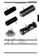
STANDARD PARTS Fig. 2 - Replacement Brushes 5 3 4 2 1 350846 - ALL Ref. 1 1 2 3 4 5 Part No. 80042 378804 80058 80355 80351 378802 3640E 330564 (02- 2000) Serial Number (000000(000000(000000(000000(000000(000000- ) ) ) ) ) ) Description Brush, Side Brush, Side STFP Brush, Sweep, 24Lg Poly Brush, Carpet Brush, Sweep, Sandwedge Brush, Sweep, P&W Qty.
STANDARD PARTS Fig.
STANDARD PARTS Fig. 3 - Main Frame Group Ref. 1 2 3 4 5 6 7 8 9 o Y Y Y Y Y Y 10 11 12 13 14 15 16 17 18 19 20 o Y Y Y Y Y 21 22 23 24 25 o Y Y Y Y Y 26 27 28 29 30 31 32 33 34 35 36 Part No.
STANDARD PARTS Fig.
STANDARD PARTS Fig. 4 - Drive System Group o Y Ref. 1 2 3 4 5 6 7 8 9 10 11 12 13 14 15 16 17 18 19 20 21 22 23 24 25 26 27 Part No.
STANDARD PARTS Fig.
STANDARD PARTS Fig. 5 - Main Brush Group o Y Y o Y Ref. 1 2 3 4 5 6 7 8 9 10 11 12 13 14 15 16 17 18 19 20 21 22 23 24 25 26 27 28 29 30 31 32 33 34 35 Part No.
STANDARD PARTS Fig.
STANDARD PARTS Fig. 6 - Side Brush Group o Ref. 1 2 3 4 5 Y Y Y Y 6 7 8 9 10 11 12 13 14 15 16 17 Part No.
STANDARD PARTS Fig.
STANDARD PARTS Fig. 7 - Hopper Group Ref. 1 2 3 4 5 6 7 8 9 10 11 12 13 14 Part No. 9005833 80958 80315 72970 373142 80141 80266 1020341 08712 09737 01685 08713 08716 32490 3640E 330564 (08- 2014) Serial Number (000000(000000(000000(000000(000000(000000(000000(000000(000000(000000(000000(000000(000000(000000- ) ) ) ) ) ) ) ) ) ) ) ) ) ) Description Hopper, Afmkt [3640] Bracket, Support Seal Rivet, Plstc Skirt, Hopper Angle, Lip Plate, Firewall Screw, Hex, M8 X 1.
STANDARD PARTS Fig.
STANDARD PARTS Fig. 8 - Vacuum Fan Group Ref. 1 2 3 4 5 6 7 8 9 10 11 12 13 14 15 16 17 18 19 20 21 22 23 24 25 26 27 28 Part No.
STANDARD PARTS Fig.
STANDARD PARTS Fig. 9 - Vacuum Housing Group o Y Y Y Ref. 1 2 3 4 5 6 7 8 9 10 11 12 13 14 15 16 17 18 19 20 21 22 23 24 25 26 27 28 29 30 31 32 33 Part No.
STANDARD PARTS Fig.
STANDARD PARTS Fig. 10 - Brush Lift Handles Group o Y Ref. 1 2 3 4 5 6 7 8 9 10 11 12 13 14 15 16 17 18 19 20 21 22 Part No.
STANDARD PARTS Fig.
STANDARD PARTS Fig. 11 - Clutch and Shift Handle Group o Y Ref. 1 2 3 4 5 6 7 8 9 10 11 12 13 14 15 16 17 Part No.
STANDARD PARTS Fig.
STANDARD PARTS Fig. 12 - Electric Motor Group o Ref. Part No.
STANDARD PARTS Fig.
STANDARD PARTS Fig. 13 - Battery Cover Group Ref. 1 2 3 4 5 6 7 8 9 10 11 12 13 14 15 16 17 18 19 20 Part No.
STANDARD PARTS Fig. 14 - Battery Cable Harness Group 1 2 3 2 3 4 3 350876 - E o Y Ref. 1 2 3 4 2- 26 Part No. 49443 49548 02076 63735 Serial Number (000000(000000(000000(000000- ) ) ) ) Description Harness, Cable Battery Connector, Andersen 50amp Red Boot, 90Deg .50D .57X .84 Cable Assy- Lead,11.0, 6Ga Qty.
STANDARD PARTS Fig. 15 - Instrument Panel Group 10 3 1 4 4 5 9 7 8 2 11 6 350880 - E o Y Ref. Part No.
STANDARD PARTS Fig.
STANDARD PARTS 3640E 330564 (08- 2001) 2- 29
STANDARD PARTS Fig. 17 - Wire Harness Group 14 6 12 6 11 VIEW C- C 0.
STANDARD PARTS Fig. 17 - Wire Harness Group 1 Ref. Part No. 80602 3640E 330564 (08- 2001) Serial Number (000000- ) Description Harness, Wire, Main E 351320 - E Qty.
STANDARD PARTS Fig. 18 - Label Group 2 1 2 4 2 2 1 2 1 3 2 5 350910 - E Ref. 1 2 3 4 5 2- 32 Part No. 80349 80206 09806 80112 1048749 Serial Number (000000(000000(000000(000000(000000- ) ) ) ) ) Description Label Set, Operational Label Set, Info & Hzd TJ Label, Tennant Logo Label, Charger Connection Label, Side [3640] Qty.
OPTIONS SECTION Contents 3 Page Fig. 1 - Hopper Dump Assist Kit . . . . . . . . . . . . . . . 3-2 Fig. 2 - Dual Side Brush Kit . . . . . . . . . . . . . . . . . . . 3-4 Fig. 3 - Panel Filter Kit . . . . . . . . . . . . . . . . . . . . . . . 3-6 Fig. 4 - Vacuum Bag Kit . . . . . . . . . . . . . . . . . . . . . . 3-8 Fig. 5 - High Flow To Standard Panel Kit . . . . . . . 3-10 Fig. 6 - Standard To High Air Flow Kit . . . . . . . . . 3-12 Fig. 7 - High Flow Vacuum Wand Kit . . . . . . . . . . 3-14 Fig.
OPTIONS Fig.
OPTIONS Fig. 1 - Hopper Dump Assist Kit o Y Y Y Y Y Y Y Ref. Part No. 80249 1 80960 2 80961 3 222403 4 80289 5 29557 6 08713 7 80300 3640E 330564 (02- 2000) Serial Number (000000(000000(000000(000000(000000(000000(000000(000000- ) ) ) ) ) ) ) ) Description Hopper Dump Assist Kit Bracket, Hopper Assist Handle, Hopper Assist Wheel, 2.O Dia Shaft, Hopper Assist Pin,Clevis,0.37 Dia.X 1.25 Lg Nut- Hxlocnyln M 8X1.25 Reg Ss Button, Wear 350894 - ALL Qty.
OPTIONS Fig.
OPTIONS Fig. 2 - Dual Side Brush Kit o Yo YY YY YY YY Y Y Y Y Y Y Y Ref. Part No. 378763 1 1056182 80125 80127 369795 369796 2 80321 3 379206 4 11516 5 80042 6 02942 7 06943 8 32490 3640E 330564 (12- 2009) Serial Number (000000(000000(000000(000000(000000(000000(000000(000000(000000(000000(000000(000000(000000- ) ) ) ) ) ) ) ) ) ) ) ) ) Description Kit, Brush, Side, Dual, 24V Motor, Ele, 24vdc 0068rpm 0.08hp 04.
OPTIONS Fig.
OPTIONS Fig. 3 - Panel Filter Kit o Y Y Y Y Y Y Y Y Y Y Y Y Y Y Y Y Y Y Y Y Y Y Y Y Ref. Part No.
OPTIONS Fig.
OPTIONS Fig. 4 - Vacuum Bag Kit o Y Y Y Y Ref. Part No. 80301 1 80103 2 80433 3 1067680 4 80288 3640E 330564 (08- 2014) Serial Number (000000(000000(000000(000000(000000- ) ) ) ) ) 350940 - ALL Description Conv Kit. Panel Filter To Bag Screen, Vacuum Bag Tube, Vacuum Bag, Vacuum, Paper [1pick=1pkg] (1 Pkg = 10 Bags) Plug Button Qty.
OPTIONS Fig.
OPTIONS Fig. 5 - High Flow To Standard Panel Kit o Yo YY YY YY YY Y Y Y Y Y Y Y Y Y Y Ref. Part No.
OPTIONS Fig.
OPTIONS Fig. 6 - Standard To High Air Flow Kit o Y Y Y Y Y Y Y Y Y Y Y Y Y Y Y Y Ref. Part No.
OPTIONS Fig.
OPTIONS Fig. 7 - High Flow Vacuum Wand Kit o Y Y Y Y Y Y Y Y Y Y Ref. Part No. 373137 1 65580 2 32492 3 39277 4 08709 5 83285 6 83289 7 9005835 8 83287 9 379204 10 80299 3640E 330564 (12- 2009) Serial Number (000000(000000(000000(000000(000000(000000(000000(000000(000000(000000(000000- ) ) ) ) ) ) ) ) ) ) ) Description Kit, Vac Wand F/Hi Air Flow Bag, Power Washer, Flat, .38 Hard Screw, Hex, M08- 1.25 X 25, 8.8 Nut, Hex, Lock, M08- 1.
OPTIONS Fig.
OPTIONS Fig. 8 - Vacuum Wand Extend Kit o Y Y Y Y Ref. Part No. 373106 1 80299 2 190039 3 80106 4 80113 3640E 330564 (12- 2009) Serial Number (000000(000000(000000(000000(000000- ) ) ) ) ) Description Kit, Vacumm Wand, Extend Coupling, Vac- Wand Tube, Extn, Blk [W- 500] Bracket, Handle, Stop Plate, Cable, Mount 352798 - ALL Qty.
OPTIONS Fig.
OPTIONS Fig. 9 - Hepa Filter Kit Ref. 1 2 3 4 5 6 7 8 9 10 11 12 13 14 15 16 17 18 19 20 21 22 23 Part No.
OPTIONS Fig.
OPTIONS Fig. 10 - Wide Track Wheels Kit o Y Y Y Y Y Y Y Y Y Y Y Y Y Y Y Y Y Y Y Y Y Ref. Part No.
OPTIONS Fig. 11 - Battery Group, 12VDC, CCA, 105AH, 130869 6 3 2 6 4 6 1 1 5 350902 - E Ref. 1 2 3 4 5 Part No. 130869 379205 80134 33671 13294 Serial Number (000000(000000(000000(000000(000000- ) ) ) ) ) 6 6 1041030 45962 (000000(000000- ) ) 3- 22 Description Battery, 12vdc, Cca, 130ah(30xhs- Wnt) Bracket, Sppt, Battery Spacer, Battery, Foam Strap, Rbr, Tie- Down, 2/Hooks 19.0l Seal, Rbr, Open, 0.50th, 1.00w 10.
OPTIONS Fig. 12 - Battery Charger Group, 24VDC/19A 50/60HZ, 1067630 1 2 08080 - E o Y Ref. Part No. 1 1067630 2 605387 3640E 330564 (03- 2013) Serial Number (000000(000000- ) ) Description Charger, 24vdc, 19a Var Vac 50/60hz (Jp) Connector, Anderson, 050a, Red [W/O Con] Qty.
OPTIONS Fig. 13 - Hinge Repair Kit 2 5 3 4 1 4 2 352794 - ALL o Y Y Y Y Y Ref. Part No. 379220 1 379221 2 363503 3 32483 4 08708 5 379219 3- 24 Serial Number (000000(000000(000000(000000(000000(000000- ) ) ) ) ) ) Description Kit, Hinge Repair Hinge, Cover Screw, Pan, M06- 1.0 X 12, Ss Washer, Flat, .25 Sae Nut, Hex, Lock, M06 Washer, Flat, Rework Qty.
OPTIONS Fig. 14 - Steel Static Chain Kit 5 3 4 3 1 2 350936 - ALL o Y Y Y Y Y Ref. Part No. 379007 1 46307 2 06943 3 32490 4 41141 5 08708 3640E 330564 (03- 2001) Serial Number (000000(000000(000000(000000(000000(000000- ) ) ) ) ) ) Description Kit, Chain, Static, Steel Chain, Link Screw, Hex, M06- 1.0 X 20, 8.8 Washer, Flat, .25 Hard Washer, Lock, Int - Ext, .31 Nut, Hex, Lock, M06 Qty.
OPTIONS Fig. 15 - Battery Cutout Button Kit 1 1 2 350918 - E o Y Y Ref. Part No. 222664 1 78553 2 65665 3- 26 Serial Number (000000(000000(000000- ) ) ) Description Battery Cutout Button Kit Switch, Pushbutton Contact, Switch Qty.
OPTIONS Fig. 16 - Carpet Sweeping Group, 105Amp hr 2 1 3 350923 - E Ref. 1 2 3 Part No. 80972 80120 378764 3640E 330564 (09- 2004) Serial Number (000000(000000(000000- ) ) ) Description Screw, 250- 20 Spl Bag, Battery Strap Qty.
OPTIONS Fig. 17 - Main Brush Downpressure Kit 1 351287 - ALL o Y Ref. Part No. 378768 1 378765 3- 28 Serial Number (000000(000000- ) ) Description Main Brush Downpressure Kit Limiter, Travel, Brush Qty.
OPTIONS Fig. 18 - Documentation Group Ref. Part No. 1 330564 Serial Number (000000- ) Description Manual Pkg 3640E JP Qty. 1 To view, print, order, download the latest Parts manual, other language Operator manuals, and Use and Care Guides (wall charts), visit: www.tennantco.
OPTIONS 3- 30 3640E 330564 (09- 2004)
BREAKDOWNS SECTION Contents 4 Page Fig. 1 - Transaxle Breakdown, 80476 . . . . . . . . . .
BREAKDOWNS Fig.
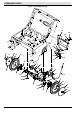
BREAKDOWNS Fig. 1 - Transaxle Breakdown, 80476 o Y Y Y Yo YY YY YY YY YY YY Ref. Part No.
BREAKDOWNS 4- 4 3640E 330564 (02- 2000)