3640 (Gas/LPG) Sweeper Operator Manual North America / International www.tennantco.com 330580 Rev.
This manual is furnished with each new model. It provides necessary operation and maintenance instructions. Read this manual completely and understand the machine before operating or servicing it. This machine will provide excellent service. However, the best results will be obtained at minimum costs if: S The machine is operated with reasonable care. S The machine is maintained regularly - per the machine maintenance instructions provided.
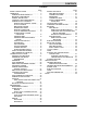
CONTENTS CONTENTS Page SAFETY PRECAUTIONS . . . . . . . . . . . . . . . . . 3 OPERATION .......................... 5 OPERATOR RESPONSIBILITY . . . . . . . . . 5 MACHINE COMPONENTS . . . . . . . . . . . . . 7 SYMBOL DEFINITIONS . . . . . . . . . . . . . . . . 8 CONTROLS AND INSTRUMENTS . . . . . . 9 OPERATION OF CONTROLS . . . . . . . . . . 10 DIRECTIONAL CONTROL LEVER . . . 10 CLUTCH HANDLE . . . . . . . . . . . . . . . . . . 12 MAIN BRUSH LEVER . . . . . . . . . . . . . . . 12 SIDE BRUSH LEVER . . . . . .
CONTENTS 2 3640 330580 (12--00)
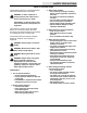
SAFETY PRECAUTIONS SAFETY PRECAUTIONS The following symbols are used throughout this manual as indicated in their description: WARNING: To warn of hazards or unsafe practices that could result in severe personal injury or death. FOR SAFETY: To identify actions that must be followed for safe operation of equipment. The machine is suited to sweep disposable debris. Do not use the machine other than described in this Operator Manual. The machine is not designed for use on public roads.
SAFETY PRECAUTIONS The following safety labels are mounted on the machine in the locations indicated. If these or any labels become damaged or illegible, install a new label in its place.
OPERATION OPERATION OPERATOR RESPONSIBILITY - The operator’s responsibility is to take care of the daily maintenance and checkups of the machine to keep it in good working condition. The operator must inform the service mechanic or supervisor when the maintenance intervals are required as stated in the MAINTENANCE section of this manual. - Read this manual carefully before operating the machine. View the operation video supplied with the machine.
OPERATION - Keep your machine regularly maintained by following the maintenance information in this manual. We recommend taking advantage of a regularly scheduled service contract from your Tennant representative. - Order parts and supplies directly from your authorized Tennant representative. Use the parts manual provided when ordering parts. - After the first 50 hours of operation, follow the recommended procedures stated in the MAINTENANCE CHART.
OPERATION MACHINE COMPONENTS G A F H C D E B 350659 A. B. C. D. E. F. G. H.
OPERATION SYMBOL DEFINITIONS These symbols identify controls, displays, and features on the machine: Start Filter shaker switch Side brush(es) down and on Side brush(es) up and off Main brush down pressure Main brush down and on Main brush up and off Low engine oil indicator Low battery / alternator indicator Circuit breaker #1 8 3640 330580 (01--00)
OPERATION CONTROLS AND INSTRUMENTS J O N M L K H I A B C F A. B. C. D. E. F. G. H. I. J. K. L. M. N. O. 3640 330580 (01--00) Main brush lever Side brush lever Directional control lever Clutch handle Steering bar Steering bar adjustment knobs.
OPERATION OPERATION OF CONTROLS DIRECTIONAL CONTROL LEVER The directional control lever controls the machine’s speed and direction of travel. The machine has three forward speeds: second, first, and third; one reverse speed; as well as neutral and park settings. The speed selection pattern is designed to allow the operator to move the control lever quickly between second speed and reverse. The neutral setting is located midway between these positions.
OPERATION NEUTRAL: Push the directional control lever halfway between the REVERSE position and the SECOND SPEED position. The machine will not move forward when the clutch handle is squeezed while in NEUTRAL. Do not leave the machine powered on in NEUTRAL while the machine is unattended. SECOND SPEED: Push the directional control lever one position forward from the NEUTRAL position. The machine will move forward when the clutch handle is squeezed. Use SECOND SPEED for normal sweeping.
OPERATION CLUTCH HANDLE The clutch handle engages the machine’s propelling system when the direction control lever is positioned in a forward or reverse position. The farther the clutch handle is squeezed toward the steering bar, the faster the machine will travel, up to its maximum in the selected position. Braking: To stop the machine at any time, regardless of direction of travel, release the clutch handle. The machine will immediately slow down, then stop completely.
OPERATION SIDE BRUSH LEVER The side brush lever raises and lowers the side brush. The side brush will rotate automatically when lowered. The side brush does not rotate when raised. Side brush down and on: Move the side brush lever to the right, out the raised position, then forward to the desired brush down pressure setting. Side brush up and off: Move the side brush lever backward, then to the left to raise and set the side brush in the raised position.
OPERATION LOW BATTERY CHARGE INDICATOR The low battery charge indicator will illuminate when the battery charging system is not functioning properly. If the light remains on after the engine starts, contact TENNANT service personnel. STEERING BAR Use the steering bar to steer the machine. STEERING BAR ADJUSTMENT KNOBS The steering bar adjustment knobs allow you to move and lock the steering bar into a position that is most comfortable for you.
OPERATION IGNITION KEY SWITCH The ignition switch turns the engine on and off using a key. On: Turn the key clockwise as far as it will go and release it to the on position. Off: Turn the key counterclockwise. HOURMETER The hourmeter records the number of hours the machine has been in use. Use this information as a guide to indicate when routine maintenance needs to be performed. VACUUM WAND (OPTION) The vacuum wand uses the machine’s vacuum system.
OPERATION CIRCUIT BREAKER The circuit breaker is a resetable electrical circuit protection device designed to stop the flow of current in the event of a circuit overload. If the circuit breaker is tripped, reset it manually by pressing the reset button after the breaker has cooled down. If the overload that caused the circuit breaker to trip is still present, the circuit breaker will continue to stop current flow until the problem is corrected. The circuit breaker Is located on the instrument panel.
OPERATION HOW THE MACHINE WORKS The operator steers the machine by using the steering bar. The directional control lever controls the forward or reverse direction of the machine. The clutch handle engages the propelling system when it is squeezed toward the steering bar. The clutch handle will also stop the machine when it is released. The side brush sweeps debris into the path of the main brush. The main brush sweeps debris from the floor into the hopper.
OPERATION - Check the engine oil level. - LPG powered machines: Check for LPG odor or frosting on hoses or components indicating an LPG leak. - Check controls for proper operation. - Check maintenance records to determine service requirements.
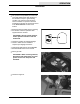
OPERATION CHANGING AN LPG TANK 1. Stop the machine in a designated safe area with the engine running. Move the directional lever into the PARK position. 2. Close the service valve on the LPG tank. 3. Allow the engine to run until it stops from lack of fuel. FOR SAFETY: When servicing machine, keep flames and sparks away from fuel system service area. Keep area well ventilated. 350412 4. Put on gloves to remove the quick-disconnect tank coupling. 5. Unlatch the clamp holding the empty tank.
OPERATION 8. Connect the LPG fuel line to the service coupling. Ensure the service coupling is clean, free of damage, and matches the machine service coupling. 350412 9. Open the tank service valve slowly. Look and listen for leaks. Close the service valve immediately if an LPG leak is found or if a strong LPG odor is detected. Notify the appropriate personnel regarding LPG fuel leaks.
OPERATION STARTING THE MACHINE 1. LPG powered machines: Open the tank service valve slowly. NOTE: Opening the service valve too quickly may cause the check valve to stop the flow of LPG fuel. If the check valve stops the fuel flow, close the service valve, wait a few seconds and open the valve again more slowly. 2. If equipped with the vacuum lockoff system; For cold and hot starting -- Pull out choke and crank engine for 3 to 5 seconds.While continuing to crank engine, siowly push in choke.
OPERATION SWEEPING AND BRUSH INFORMATION Pick up oversized debris before sweeping. Flatten or remove bulky cartons from aisles before sweeping. Pick up pieces of wire, twine, string, etc., which could become entangled in the brushes or brush hub. Plan the sweeping in advance. Try to arrange long runs with minimum stopping and starting. Sweep debris from very narrow aisles into the main aisles ahead of time. Do an entire floor or section at one time. Drive the straightest path possible.
OPERATION SWEEPING 1. Drive the machine to the area to be swept. 2. Release the clutch handle to stop the machine. 3. Move the main brush lever to the left, out of the raised position, then allow it to fall forward into the sweeping position. 4. Move the side brush lever to the right, out of the raised position, then forward to the desired brush down pressure setting. 5. Squeeze the clutch handle to begin sweeping. 6. Sweep as needed.
OPERATION STOP SWEEPING 1. Release the clutch handle. NOTE: The machine will immediately slow down, then stop completely. 2. Move the main brush lever backward, then to the right to raise and set the main brush in the raised position. 3. Move the side brush lever backward, then to the left to raise and set the side brush(es) in the raised position.
OPERATION 4. Move the directional control lever into the PARK position. 5. Shake the panel filter by pressing the filter shaker switch. The shaker motor will operate for 15 seconds before stopping. NOTE: Make sure the filter compartment is closed securely before activating filter shaker. 6. Turn the machine power off. 7. LPG powered machines: Ensure the LPG tank service valve is closed.
OPERATION EMPTYING THE DEBRIS HOPPER STANDARD HOPPER Drive the machine to the area where debris is collected. Turn the machine power off. WARNING: Brush throws debris. Stop motor before lifting hopper. The debris hopper is equipped with one center, and two side finger grips to allow two people to lift and empty the hopper. Pull the hopper slightly forward to unseat it from the machine frame. With one person on each side, lift the debris hopper out of the machine.
OPERATION HOPPER DUMP ASSIST HANDLE (OPTION) The dump assist handle allows easy removal and transport of the debris hopper when it is full. Turn the machine power off. WARNING: Brush throws debris. Stop motor before lifting hopper. Raise the dump assist handle. Place one foot on the hopper’s pivot point. Lift the hopper out of the machine and onto the wheels. Transport the hopper to the location where debris is collected. WARNING: Heavy hopper. Get help to handle.
OPERATION REPLACING THE BAG FILTER (OPTION) The bag filter (option) traps dust and small particles of debris. Check the bag filter daily and replace it when it becomes full of debris. To access the bag filter, remove the vacuum wand and unlatch the filter compartment hooks. Install a new bag filter by placing the cardboard tab on the filter around the vacuum inlet tube. The vacuum inlet tube is located at the top of filter compartment, on the inside of the machine. Latch the filter compartment door.
OPERATION CLEANING THE FILTER COMPARTMENT The panel filter traps dust and small particles of debris. Press the filter shaker switch to shake the debris from the panel filter each time the hopper is emptied. This debris collects in the filter compartment. Clean the filter compartment daily. Remove the vacuum wand and unlatch the filter compartment hooks. Lower and remove the filter compartment door by sliding it to the left off the pivot pins. Empty the dust and debris.
OPERATION POST-OPERATION CHECKLIST Check this list of items after sweeping and emptying hopper: - Check for wire or string tangled in the bristles of the main brush and side brush(es). Additional side brush option shown. FOR SAFETY: Before leaving or servicing machine, stop on level surface, turn off machine, and remove key. - Check and, if necessary, wipe the vacuum inlet plate clean. - LPG powered machines: Ensure the LPG tank service valve is closed. - Check for fuel odor that indicates a fuel leak.
OPERATION OPTIONS WIDE TRACK TIRES AND HEAVY DUTY CASTERS Wide track tires and heavy duty casters provide increased maneuverability and control on rough surfaces.
OPERATION MACHINE TROUBLESHOOTING Problem Cause Remedy Excessive dusting Vacuum hose clogged Unscrew hose from vac wand handle and clean Brush skirts and dust seals worn or damaged Replace brush skirts or dust seals Filter bag full or panel filter clogged Shake and / or clean or replace bag or panel filter Vacuum wand hose damaged Replace vacuum wand hose Vacuum wand not fully inserted into machine Insert fully Vacuum inlet plate clogged Remove / clean plate.
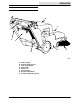
MAINTENANCE MAINTENANCE 1 6 2 3 4 5 7 8 350841 MAINTENANCE CHART Interval Daily Key Description 1 Engine oil 4,5 Main brush and side brush(es) 2 Skirts and seals 6 Bag filter (option) 6 Panel filter 2 1 1 1 5 Vacuum inlet plate Engine oil Engine air filter Vacuum fan belt Main brush 100 Hours 6 7 8 200 Hours 1 1 500 Hours 3 Panel filter Wide track tires (option) Heavy duty casters (option) Sparkplug Gasoline fuel filter / sediment bowl Side brush motor(s) 50 Hours Procedure Check with dip
MAINTENANCE LUBRICATION ENGINE Use the dipstick to check the engine oil level daily. Change the engine oil after every 50 hours of operation. Use a straight SAE 30--weight, API class CD / SF or higher engine oil. If multiviscosity oil is used, oil consumption and combustion deposits will increase. Using oil other than service class SF, or extending oil exchange intervals can cause engine damage not covered by the engine warranty. The engine oil capacity is 0.65L (1.4 pt).
MAINTENANCE FUEL SYSTEM FUEL FILTER AND SEDIMENT BOWL Gasoline powered machines are equipped with a fuel filter and a sediment bowl to clean the fuel and collect the debris. The fuel filter and sediment bowl are located below the gasoline tank. Remove and clean these components every 200 hours of machine use. FOR SAFETY: When servicing machine, keep flames and sparks away from fuel system service area. Keep area well ventilated.
MAINTENANCE ENGINE AIR FILTER Unlatch the clamp on the side of the filter assembly to remove the air filter. Replace the air filter after every 50 hours of operation. SPARKPLUG Replace, or clean and set the gap of the sparklug after every 200 hours of use. The proper sparkplug gap is 0.75 mm (0.03 in).
MAINTENANCE SKIRTS AND SEALS MAIN BRUSH SKIRTS The main brush skirts are located at the ends of the main brush. These skirts are designed to deflect debris into the hopper. Check the brush skirts for damage or wear daily. HOPPER DUST SEAL The hopper dust seal, located at the top of the hopper compartment, helps maintain a vacuum within the hopper. Check the hopper dust seal for damage or wear daily. REAR SKIRT The rear skirt, located behind the main brush, helps create a vacuum around the main brush.
MAINTENANCE HOPPER LIP SKIRT The hopper lip skirt, located on the lip of the hopper, ensures debris thrown from the main brush will go into the hopper. Check the hopper lip skirt for damage or wear daily. FILTER COMPARTMENT DOOR SEAL The filter door seal, located around the perimeter of the filter compartment door, helps maintain a vacuum around the filter. Check the filter compartment door seal for damage or wear daily.
MAINTENANCE CLEANING THE PANEL FILTER The panel filter filters the air pulled up from the hopper. The panel filter is equipped with a shaker to remove the accumulated dust particles. Remove and thoroughly clean the panel filter after every 100 hours of use. To remove the panel filter, unlatch and lower the filter compartment door. Unlatch the panel filter retainer and remove the filter.
MAINTENANCE BRUSHES MAIN BRUSH The main brush spans the width of the machine and throws debris into the hopper. Check the brush for damage and wear daily. Remove string or wire tangled in the main brush or the main brush hub. Check the main brush pattern after every 50 hours of use. Adjust the main brush pattern by loosening the nut at the left end of the brush arm crossbar. Rotate the main brush after every 50 hours of use for maximum brush life and sweeping performance.
MAINTENANCE 3. Remove the debris hopper. 4. Pull the string guard and skirt back to avoid damaging. 5. Pull the main brush out of the machine through the hopper opening. 6. Remove the brush hub from the worn brush and install it into the new brush. 7. Install the new main brush into the machine. 8. Insert the main brush pin through the hole in the frame and into the main brush hub. Turn the main brush pin 1/4 turn clockwise. 9. Replace the hopper.
MAINTENANCE CHECKING AND ADJUSTING MAIN BRUSH PATTERN 1. Apply chalk (or another material that will not easily blow away), to a smooth, level section of the floor. 2. Lower the main brush in the chalked area. Allow the machine to sweep in the same place for 15 to 20 seconds. NOTE: If chalk or other material is not available, allow the brush to spin on the floor for two minutes. A polish mark will remain on the floor. 3. Raise the main brush and move the machine away from the chalked area.
MAINTENANCE ROTATING THE MAIN BRUSH 1. Turn the machine power off and move the directional lever into the PARK position. FOR SAFETY: Before leaving or servicing machine, stop on level surface, turn off machine, and remove key. 2. Turn the main brush pin 1/4 turn counter--clockwise and remove. 3. Remove the debris hopper. 4. Pull the main brush out of the machine through the hopper opening. 5. Remove the brush hub from the main brush and install it into the other end. 6.
MAINTENANCE SIDE BRUSH(ES) The side brush(es) sweep debris along walls and edges into the path of the main brush. Check the side brush(es) for damage and wear daily. Remove string or wire tangled in the side brush(es). A side brush should be replaced when it no longer effectively sweeps for your application. REPLACING THE SIDE BRUSH(ES) 1. Turn the machine power off and move the directional lever into the PARK position.
MAINTENANCE BELTS AND CHAINS VACUUM FAN BELT The vacuum fan belt drives the vacuum system. Check the belt for wear and tension after every 50 hours of operation. Check belt tension by applying a force 1 kg (2 lb) at belt midpoint. The proper deflection should be 5 mm (0.09 in). WARNING: Moving belt and fan. Keep away. MAIN BRUSH BELT The main brush drive belt is located behind the right rear tire. The belt drives the main brush. The proper belt tension is automatically set by a spring--loaded idler.
MAINTENANCE TIRES (OPTION) The optional heavy duty rear tires are pneumatic. Check the rear tires after every 100 hours of operation for damage. Check the rear tire pressure after every 100 hours of operation. The proper tire pressure is 345 kPa (50 psi).
MAINTENANCE PUSHING AND TRANSPORTING THE MACHINE PUSHING THE MACHINE If the machine becomes disabled, it can be easily pushed in neutral if necessary. TRANSPORTING THE MACHINE 1. Position the front of the machine at the loading edge of the truck or trailer. FOR SAFETY: Use truck or trailer that will support the weight of the machine. NOTE: Empty the hopper before transporting the machine. 2.
MAINTENANCE 5. Block the machine tires and place the directional control lever in Park. Tie down the machine to the truck or trailer before transporting. Secure the rear of the machine by wrapping straps around each end of the the handle and fastening them to the truck or trailer. Secure the front of the machine by wrapping a strap around the hopper and fastening it to the truck or trailer. 6.
MAINTENANCE STORING MACHINE When storing the machine for extended periods of time, the following procedures must be followed: 1. Raise the main and side brush(es). 2. Empty and clean the debris hopper. 3. Drain or disconnect and remove (LPG tank) fuel system. 4. Close the gasoline valve. 5. Change the engine oil. 6. Remove the spark plug, pour 30 cc (1 oz) of engine oil into the cylinder. Slowly rotate the crankshaft to distribute the oil. Replace the spark plug. 7. Clean the engine cooling fins. 8.
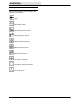
SPECIFICATIONS SPECIFICATIONS GENERAL MACHINE DIMENSIONS/CAPACITIES Item Dimension/capacity Length (Low / High steering bar position) 1428 / 1475 mm (56.25 / 58 in) Width 820 mm (32.25 in) Width (Wide track wheel kit option) 933 mm (36.75 in) Height (Low / High steering bar position) 880 / 960 mm (34.7 / 37.7 in) GVWR -- Gasoline engine 206 kg (455 lb) GVWR -- LPG engine 220 kg (485 lb) Track 775 mm (30.50 in) Wheelbase 490 mm (19.
SPECIFICATIONS POWER TYPE Engine Type Ignition Cycle Aspiration Cylinders Bore Stroke OHV Gas -magneto 4 Natural 1 49 mm (1.93 in) 67 mm (2.14 in) LPG -- Solid State Displacement Net power, governed Net power, maximum 172 cc (10.5 cu in) 3.6 hp @ 2400 rpm 6 hp @ 4000 rpm Fuel Cooling system Electrical system Air Automotive regular gasoline, 87 octane minimum, unleaded. Fuel tank: 3.6L (0.95 gal) Alternator output 13.5 V / 9.
SPECIFICATIONS 610 mm (24 in) 820 mm (32.25 in) 815 mm (32 in) 1475 mm (58 in) 960 mm (37.
INDEX INDEX B Specifications, 51 Bag filter replacement, 28 F Battery, low charge indicator, 14 Belts Main brush, 45 Vacuum fan, 45 Filter compartment, Cleaning panel filter compartment, 29 Braking, stopping machine, 12 Filters Air filter (engine), 36 Bag filter replacement, 28 Panel filter cleaning, 39 Filter shaker switch (option), 16 Brush information, 22 Brushes Main brush, 40 Main brush pattern, checking, adjusting, 42 Main brush, rotation, 43 Replacing main brush, 40 Replacing side brush(es),
INDEX M Machine, Storage, 49 Machine components, 7 Machine dimensions, 52 Machine troubleshooting, 32 Main brush, 40 Checking and adjusting brush pattern, 42 Replacement, 40 Rotation, 43 S Safety Labels, 4 Precautions, 3 Side brush lever, 13 Side brush(es) replacement, 44 Maintenance, Recommended, 6 Skirts and seals Filter compartment door seal, 38 Hopper dust seal, 37 Hopper lip skirt, 38 Main brush skirts, 37 Rear skirt, 37 Maintenance chart, 33 Sparkplug, 36 Motors, electric, 44 Specifications Cli