
Integration Guide


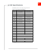


Table Of Contents

Rev 1 Dec.17 6 41111980
2
2: Power
Power Supply
The host provides power to the EM7565 through multiple power and ground pins. The
host must provide safe and continuous power (via battery or a regulated power
supply) at all times; the module does not have an independent power supply, or
protection circuits to guard against electrical issues.
For detailed pinout and voltage/current requirements of this module, see the AirPrime
EM7565 Product Technical Specification.
Module Power States
The module has five power states, as described in Table 2-1.
Table 2-1: Module Power States
State Details
Host is powered
USB interface active
RF enabled
Normal
(Default
state)
• Module is active
• Default state. Occurs when VCC is first applied, Full_Card_Power_Off# is deasserted
(pulled high), and W_DISABLE# is deasserted
• Module is capable of placing/receiving calls, or establishing data connections on the
wireless network
• Current consumption is affected by several factors, including:
• Radio band being used
• Transmit power
• Receive gain settings
• Data rate
Low power
(‘Airplane
mode’)
• Module is active
• Module enters this state:
• Under host interface control:
· Host issues AT+CFUN=0 (AT Command Set for User Equipment (UE) (Release 6)
(Doc# 3GPP TS 27.007))), or
· Host asserts W_DISABLE#, after AT!PCOFFEN=0 has been issued.
• Automatically, when critical temperature or voltage trigger limits have been reached))
Sleep • Normal state of module between calls or data connections
• Module cycles between wake (polling the network) and sleep, at network provider-deter-
mined interval.