
Owner's manual


10.
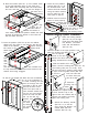
Set the unit upright and attach the coat rod brackets
(Ref. No. 9) to the underside of
the shelf, inserting one bolt
and nut through the hole
provided on the far right
and far left side of the
shelf. The open side of
each bracket should face
into the unit (see below).
Insert the coat rod (Ref.
No. 10) into first one
bracket, and
then into
the other
by flexing
the second
bracket.
1. Place the locking handle
(Ref. No. 13) on the right
hand door and fasten with
two #8-32 x 1/4 slotted
bolts and lock-washers
(Ref. No. 18).
Handle/Locking System Installation
B
A
5. Attach the "dummy" handle
(Ref. No. 17) to the left
door using two #8-32 x 1/4
slotted bolts and lock-
washers (Ref. No. 18).
8. Place the bottom (Ref. No. 7) in the lowest notch
of the shelf adjusting strips on the sides and
back. Make sure the flange with two holes faces
the front, and that it is over the flange of
the frame sill. If
necessary,
you may
push out on
the side walls to
enable the bottom to
more easily slide into position. Attach the shelf
securely by bolting the bottom to the frame sill
with two bolts and nuts.
Two holes
must be in front.
Underside of
Shelf
Left
Panel
of
Cabinet
9.
I
nsert the partition (Ref. No. 8) into the cabinet,
aligning the four holes in the partition with the two
holes in the cabinet bottom and the
two holes in the cabinet shelf.
Attach with
four
bolts
and
nuts,
mak-
ing
sure that the bolts are inserted from
the top downward to prevent items stored on the
shelves from being snagged.
4. Place the
locking cam re-
tainer
(Ref. No. 16)
over the square shank of
the door handle. Tap on the
edges of the cam retainer with a
hammer until retainer sits firmly
against the locking cam.
3. With the handle still in the open
position, hook the locking bars (Ref. No. 12)
to the locking cam (see "A" at left). Then,
hold the lock bars in position while sliding
the nylon lock bar guide inserts (Ref. No.
15) over the lock bar ends and
through the door slots (see
(see "B" at left).
2. Turn the handle to the open position, and
place the locking cam (Ref. No.14)
over the square
shank of the door
handle. The latch must be
facing downward as shown.
11. Insert the four partition
shelves (Ref. No. 11) at
the desired levels. The
shelves should be inserted
using the same method
used to place the top
shelf (refer to step 4).
12. Cabinet must be level for
doors to close properly.
Levelers may be
adjusted by plac-
ing a screwdriver
through the hole in each
end of the sill and
adjusting the leveling screw.
Insert shelf into
bottom lances.
Leveler
Access H
oles
B