Copyright © Terabee 2018 User Manual for TeraRanger Hub Evo Hardware revision 1.0 Firmware revision 1.0.0 . Terabee Website: 90 Rue Henri Fabre Technical support: 01630, Saint-Genis-Pouilly Commercial: www.teraranger.com support@teraranger.com teraranger@terabee.
Copyright © Terabee 2018 Table of contents: 1 Introduction 3 2 Mechanical Integration 3 2.1 Mechanical Design 3 2.1 Compatibility with TeraRanger Evo 4 2.2 Handling during system assembly 5 2.3 Electrical characteristics 8 2.4 Additional interface for custom requirements 8 3 USB interface 9 3.1 Connecting the TeraRanger Hub Evo to a Host Computer 3.1.1 Prerequisites 9 9 3.1.2 Terminal Emulation Software 9 3.2 Graphical User Interface 10 3.2.2 Basic Operation 10 3.2.
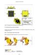
Copyright © Terabee 2018 1 Introduction The purpose of this document is to give guidelines for use and integration of the TeraRanger Hub Evo board using a USB communication interface. Instructions on how to use hub’s onboard Internal Measurement Unit (IMU) are available in section 4.5 2 Mechanical Integration 2.1 Mechanical Design Figure 1. TeraRanger Hub Evo external dimensions TeraRanger Hub Evo external dimensions are illustrated in Figure 1.
Copyright © Terabee 2018 2.1 Compatibility with TeraRanger Evo Up to 8 TeraRanger Evo distance sensors can be connected to the Hub Evo board for multi-axis, multi-sensor ranging operations. TeraRanger Evo sensors use a two-part construction where the black colored optical sensor module simply clips to the yellow colored backboard for power management and communication. Figure 2.
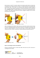
Copyright © Terabee 2018 Figure 3. TeraRanger Evo Hub backboard external dimensions 2.2 Handling during system assembly Please follow these simple steps showing how to connect 8 TeraRanger Evo sensors to the TeraRanger Hub Evo. Step 1. Connecting the cable to the sensor Start by plugging the flat flex cables (FFC) to the sensor’s FFC connector. Figure 4. Open, Insert, Close (sensor) . Terabee Website: 90 Rue Henri Fabre Technical support: 01630, Saint-Genis-Pouilly Commercial: www.teraranger.
Copyright © Terabee 2018 Note that each of the FFC connectors need to be manually opened and then closed when connecting the Flex Cables as shown in Figure 4. For easier opening you can gently pull the small locking ‘tabs’ on the sides of the connector before pulling the locking mechanism down. You may find this easier with tweezers. The locking mechanism has to be pulled out only a millimeter or less, not entirely! Note that, too much force can damage the sensors’ connector.
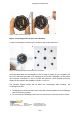
Copyright © Terabee 2018 Figure 7. Open, Insert, Close (hub) Step 3. Connecting all Evo sensors to the Hub Evo Continue connecting the rest of the Evo sensors to the central Hub board. Figure 8. TeraRanger Hub Evo with 8 sensors connected Once fully assembled, the TeraRanger Hub Evo is ready for testing on your computer. Use the micro USB cable (provided in the package) to connect the TeraRanger Hub Evo with a host computer.
Copyright © Terabee 2018 ● ● Take all usual precautions for sensitive electronics such as maintaining a suitable distance from strong electric and magnetic fields, strong radio emitters, etc. During assembly and integration, please observe all common ESD precautions 2.3 Electrical characteristics DC electrical characteristics TeraRanger Hub Evo is powered by an external power source, and can not be directly powered by USB.
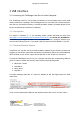
Copyright © Terabee 2018 3 USB interface 3.1 Connecting the TeraRanger Hub Evo to a Host Computer The TeraRanger Hub Evo can be easily connected to a Host Computer via the micro USB cable provided in the package. The TeraRanger Hub Evo can interact as a virtual COM port, and data can be streamed directly to terminal emulation software (Terabee advises to use HTerm for Windows and CoolTerm for MacOS). 3.1.
Copyright © Terabee 2018 Figure 10. Communication with H-Term To communicate with the Hub Evo via the terminal emulation software, you need to send a command in hexadecimal via the “Type” box. For this, select the “HEX” Type as illustrated in the figure above. Figure 10 shows an example of the command which allows data to be shown in TEXT mode. All commands are detailed in section 4. In MacOS, Terabee advises the use of Coolterm for terminal emulation software. 3.
Copyright © Terabee 2018 Figure 11. Graphical User Interface # Display Description 1 Measurement Provides up to 8 distance values in millimeters. Sensors are numbered as on the Hub Evo board. Example: TR Evo 3 will stream distance data connected to connector Nr 3 on Hub Evo. In case “-1” value is received, no sensor is connected or not able to measure. In case “+Inf” is received, the measurement is out of range. In case “-Inf” is received, the measurement is below minimum range.
Copyright © Terabee 2018 5 Update Rate Select four options of sensor measurement update rate from a drop-down menu. Choose between 50Hz, 100Hz, 250Hz, or ASAP (As Soon As Possible). 6 IMU Enable or disable the option for Inertial Measurement Unit readings. Three IMU modes are available for preview: Euler mode, Quaternion mode, Quaternion and Linear Acceleration mode. 3.2.3 Firmware Upgrade The current firmware version on your TeraRanger Hub Evo can be found by selecting Help > About in the GUI.
Copyright © Terabee 2018 3.4 LEDs In total, four LEDs are mounted on TeraRanger Hub Evo to give visual feedback on the sensor performance. Table 2 lists the functionality of each LED: LED color Description Hub Visual PWR (orange) LED continuously on connected to a power supply LED 0 (blue) One blink for each TeraRanger Evo Hub sensor detected by the Hub Evo. whenever Example: if 6 sensors are connected, the blue LED will blink 6 times before sending distance data.
Copyright © Terabee 2018 4 Communication and Modes The current Hub Evo firmware (1.0.0) provides four parameters for optimization of Hub Evo performance. The following parameters can be configured: 1. Printout modes 2. Operating modes 3. Update rate modes 4. IMU modes Figure 12 illustrates the logic of available parameters on Hub Evo. Please note all commands to be sent via terminal emulation software are in hexadecimal format. Figure 12. TeraRanger Hub Evo modes .
Copyright © Terabee 2018 For each command sent to Hub Evo, a response is generated to inform the user whether the command has been validated. Command responses consist of four bytes and is a hexadecimal value. Please note that it is crucial to receive an answer to a command, before communicating the next one. For more information on response values, please read Annex 1. 4.
Copyright © Terabee 2018 4.2.
Copyright © Terabee 2018 If the target is too close from the TeraRanger Evo Hub sensor (below the minimum distance), the associated distance value is replaced by the hexadecimal value 0x0000. If the target is too far from the TeraRanger Evo Hub sensor (above the maximum distance), the associated distance value is replaced by the hexadecimal value 0xFFFF. 4.3 Operating modes The current Hub Evo firmware provides two operating modes: (1) Simultaneous mode and (2) Sequential mode.
Copyright © Terabee 2018 4.4.1 Commands Action Type Update rate Hex Command Modify update rate ASAP (default) 00 52 03 01 CA 50 Hz 00 52 03 02 C3 100 Hz 00 52 03 03 C4 250 Hz 00 52 03 04 D1 4.5 Internal Measurement Unit (IMU) options TeraRanger Hub Evo provides an onboard IMU, supporting users with spatial orientation data. By default the IMU is disabled. Three modes are available: 1. Euler mode, 2. Quaternion mode, 3. Quaternion and Linear Acceleration mode.
Copyright © Terabee 2018 Figure 13. Roll, pitch, heading When enabling Euler mode, the displayed values are in degrees. Please see below the corresponding scaling for each of the axes: 1. 2. 3. Heading angle goes from 0° to 360°, 0° meaning North Pitch goes from -180° to +180° Roll values are in the interval ]-90°;+90°[ and will loop twice. Please note that 0° for pitch and roll angle means that the TeraRanger Evo Hub is horizontal.
Copyright © Terabee 2018 Figure 14. x, y, z axis Please note that X axis is opposite to pitch axis, Y axis is opposite to roll axis and Z axis is opposite to Z axis (Figure 14). Quaternions and linear acceleration Quaternions and linear acceleration mode displays the same coefficient as the quaternion mode, however it also gives the linear acceleration of the IMU in milli-g. Please refer to figure 14.
Copyright © Terabee 2018 4.5.1 Commands Action Type Mode name Hex Command Modify IMU mode Activate Quaternion mode 00 41 02 40 Activate Euler mode 00 41 03 47 Activate Quaternion & Linear acceleration mode 00 41 04 52 Deactivate IMU 00 41 01 49 4.5.
Copyright © Terabee 2018 - - Quaternion and Linear acceleration Euler angles (2 bytes per angle), each two bytes represent a signed 16 bit value. You need to divide those three values by 16 to convert them in degree. Checksum (1 byte) of previous 9 bytes: CRC8 Data output (18 bytes message): IM 0x03 WW XX YY ZZ XX YY ZZ CRC8 - - - - Header (two characters): I (73 decimal / 0x49 hex) and M (77 decimal / 0x4D hex) Mode (1 byte) This byte indicates in which IMU mode you are.
Copyright © Terabee 2018 Quaternion Data output: IM\t www\txxx\tyyy\tzzz\r\n - Quaternion and Linear acceleration Header (two characters): I (73 decimal / 0x49 hex) and M (77 decimal / 0x4D hex) Tabulation: \t (9 decimal / 0x09 hex) Orientation data in quaternion format.You need to divide those four values by 2^14.
Copyright © Terabee 2018 Annex 1 For each command sent to Hub Evo, a response is generated to inform the user whether the command has been validated. It is important to receive a response value before proceeding with the next command. Sending commands too early may discard the one still processing. Response commands consist of four bytes and are a hexadecimal value.