
User Manual

1Introduction
The purpose of this document is to give guidelines for use and integration of the TeraRanger
Evo 60m and TeraRanger Evo 600Hz distance sensors with (a) UART/I2C backboard,
and/or (b) USB backboard using these standard communication interfaces.
2Mechanical integration
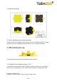
The mechanical design of the main sensor module (black) allows easy assembly to its
backboard (yellow) using a simple ‘clip-in’ technique. (When you clip the two together,
ensure there is no visible gap between the black and yellow parts.) The yellow backboard
has two mounting holes for final installation. A yellow sticker is applied on TeraRanger Evo
600Hz to differentiate it from TeraRanger Evo 60m.
When choosing a place for mounting, please consider the following recommendations:
● Choose a place which is in accordance with the optical constraints listed below
● Mounting close to sources of heat or strong electromagnetic fields can decrease the
sensing performance
● Do not mount anything directly in front of the sensor or in a cone of approximately
+/-15° around the central optical axis of the sensor
● Within the first meter from the sensor, avoid objects with high surface reflectivity in a
cone of approximately +/-45° around the central optical axis of the sensor
● It is better to avoid having other sources of Continuous Wave or modulated IR light
close to the sensor
● Please consider that dust, dirt and condensation can affect the sensor performance
● It is not advised to add an additional cover in front of the sensor
● Drone rotor blades, or other environments with flickering (‘chopped’) ambient light in
the field of view can affect sensors’ readings
Copyright © Terabee 2018
Terabee, 90 Rue Henri Fabre, 01630, St Genis-Pouilly, France
3/13