
User Manual

4.2.1
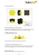
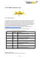
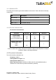
Backboard LEDs
Five LEDs are mounted to give visual feedback on the sensor. Table 2 lists the functionality
of each LED:
LED
Description
PWR (orange)
Power indicator, on when 5V connected
Rx/Tx (red/green)
UART receive and transmit indicators
LED 0 / LED 1
For internal use only
4.2.2
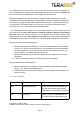
Electrical characteristics
DC electrical characteristics
Parameter
Minimum
Typical*
Maximum
Power supply
Voltage input (V)
Current consumption (mA)
4.75
130
5
*180
5.25
240
Interface logic levels
(referenced to +3V3)
LOW
HIGH
-
2.3
-
-
1
-
* Value recorded while reading a target at 2m distance. NB: this value depends on ambient
conditions, distance and target reflectivity
4.3I2C protocol information
The communication parameters are:
Frequency: 400kHz
Primary Address Length: 7-bit
Primary Slave Address: 0x31
Built-in pull-up resistors: 10kOhms on SDA and SCL (avoid additional pull-up
resistors on the same bus to prevent transmission problems)
Copyright © Terabee 2018
Terabee, 90 Rue Henri Fabre, 01630, St Genis-Pouilly, France
9/13