User Manual for TeraRanger Evo single point distance sensors and backboards
Table of contents: 1 Introduction 3 2 Mechanical integration 3 2.1 Mechanical design 4 2.2 Sensor handling during system assembly 3 USB backboard use 5 5 3.1 Graphical User Interface (version 1.0.3) 3.1.1 Prerequisites 3.1.2 Basic Operation 5 5 6 3.1.3 Firmware Upgrade 6 3.2 Connecting the TeraRanger Evo to a Host Computer 4 I2C/UART backboard use 7 8 4.2 I2C/UART interface 8 4.2.1 Backboard LEDs 9 4.2.2 Electrical characteristics 9 4.
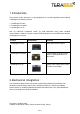
1 Introduction The purpose of this document is to give guidelines for use and integration of the following TeraRanger Evo distance sensors: 1. TeraRanger Evo 60m 2. TeraRanger Evo 600Hz 3. TeraRanger Evo 3m with (a) UART/I2C backboard, and/or (b) USB backboard using these standard communication interfaces. Please consult the following table for visual differences between TeraRanger Evo sensors.
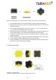
When choosing a place for mounting, please consider the following recommendations: ● ● ● ● ● ● ● ● Choose a place which is in accordance with the optical constraints listed below Mounting close to sources of heat or strong electromagnetic fields can decrease the sensing performance Do not mount anything directly in front of the sensor or in a cone of approximately +/-15° around the central optical axis of the sensor Within the first meter from the sensor, avoid objects with high surface reflectivity in a c
2.2 Sensor handling during system assembly During assembly and integration, please observe all common ESD precautions. All optical surfaces (sensor front) should be kept clean and free from contact with chemicals. 3 USB backboard use The USB backboard comes with a standard Micro-USB connector. 3.1 Graphical User Interface (version 1.0.3) A free Graphical User Interface (GUI) is available, providing an easy way to visualize the data from your TeraRanger Evo.
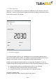
3.1.2 Basic Operation Make sure your TeraRanger Evo is connected to a USB port on your computer. In the GUI select File > Connect. You should immediately see a distance reading in millimetres and the status should change to ‘Connected’. 3.1.3 Firmware Upgrade The current firmware version on your TeraRanger Evo can be found by selecting Help > About in the graphical user interface.
● ● ● ● ● You will be presented with a dialog window asking you to confirm your choice After confirming your choice, a new dialog window will present you with instructions on selecting the firmware file and launching the upgrade process, read the instructions carefully. Press ‘Select File’ and select the new firmware file with Windows File Explorer Press ‘Upgrade’ and wait until the operation finishes Close the Upgrade dialog box 3.
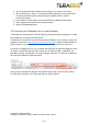
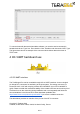
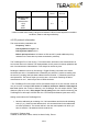
To communicate with the terminal emulation software, you need to send a command in hexadecimal via the “Type” box. First check the “Hex” checkbox and choose the “HEX” Type. The figure above shows an example of the command which allows data to be shown in TEXT mode. 4 I2C/UART backboard use 4.2 I2C/UART interface The TeraRanger Evo can be controlled through I2C or UART interfaces. It uses a single 9 pin Hirose DF13 connector for interfacing to the host system.
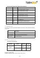
Pin out and description (According to DF13 datasheet) Pin Designator Description 1 Tx UART transmit output. 3.3V logic 2 Rx UART receive input. 3.3V logic 3 GND Power supply and interface ground 4 SDA I2C serial data line. 3.3V logic 5 SCL I2C serial clock line. 3.3V logic 6 rfu RESERVED FOR FUTURE USE 7 5V +5V supply input 8 GND Power supply and interface ground 9 rfu RESERVED FOR FUTURE USE 4.2.1 Backboard LEDs Five LEDs are mounted to give visual feedback on the sensor.
Evo 3m Interface logic levels (referenced to +3V3) LOW HIGH 4.75 V 70 mA 5.25 V 250 mA 2.3 1 - * Value recorded while reading a target at 2m distance. NB: this value depends on ambient conditions, distance and target reflectivity 4.
2. Send the desired command listed in the table below (see table below in the next paragraph) 3. In case the command creates an answer, read it back immediately Reading data from the TeraRanger Evo: 1. Send the address byte consisting of 7 bit base address and the last bit indicating read (‘1’), e.g. 0x63 for base address 0x31 2. Read back the the number of bytes imposed by the command, e.g. three bytes for a distance reading 4.3.
4.4 UART Communication 4.4.1 UART protocol information The UART communication for the TeraRanger Evo uses a simple Modbus-like protocol. The communication parameters are: Baud Rate: 115 200 Data Bits: 8 Stop Bit(s): 1 Parity: None HW Flow Control: None 4.4.2 Commands Address Command Data CRC-8 0x00 PRINTOUT MODE 0x11 TEXT 0x01 0x45 0x00 PRINTOUT MODE 0x11 BINARY 0x02 0x4C The default mode of TeraRanger Evo is Binary mode.
*please be aware that there is no zero-padding for leading zeros! - If the TeraRanger Evo is unable to measure a distance, it will output -1\n as an error message - If the target is too close (below the minimum distance), the TeraRanger Evo will output -Inf\n - If the target is too far away (above the maximum distance), the TeraRanger Evo will output +Inf\n Binary output Data output (4 bytes message): TXXCRC8 - Header (1 byte): T (84 decimal / 0x54 hex) Distance reading in millimeters** (2 bytes): XX C
5 Declaration of Conformity CE certified, eye-safe and RoHS compliant TeraRanger Evo 3m complies with IEC 62471:2006, eye safety certification. Further certifications for Evo 3m sensor pending.