User Manual for TeraRanger Evo single point distance sensors and backboards TeraRanger TeraRanger TeraRanger TeraRanger Evo 60m Evo 40m Evo 15m Evo 3m USB backboard I2C backboard Technical support: s upport@teraranger.com Sale s and comm e rcia l su pp o rt : terabee-sales@terabee.
Table of contents: 1 Introduction 3 2 Mechanical integration 4 2.1 Mechanical design 4 2.2 Sensor handling during system assembly 5 3 USB backboard use 5 3.1 Graphical User Interface (version 1.0.3) 5 3.1.1 Prerequisites 6 3.1.2 Basic Operation 6 3.1.3 Firmware Upgrade 7 3.2 Connecting the TeraRanger Evo to a Host Computer 4 I2C/UART backboard use 8 9 4.2 I2C/UART interface 9 4.2.1 Backboard LEDs 10 4.2.2 Electrical characteristics 10 4.
1 Introduction The purpose of this document is to give guidelines for use and integration of the following TeraRanger Evo distance sensors: 1. TeraRanger Evo 60m 2. TeraRanger Evo 40m 3. TeraRanger Evo 15m 4. TeraRanger Evo 3m with (a) UART/I2C backboard, and/or (b) USB backboard using these standard communication interfaces. Please consult the following table for visual differences between TeraRanger Evo sensors. Product Visualization Hardware TeraRanger Evo 60m Black optical sensor module.
TeraRanger Evo 3m Sensor’s lens surface is flat, unlike Evo 60m, 40m, 15m. 2 Mechanical integration The mechanical design of the main sensor module (black) allows easy assembly to its backboard (yellow) using a simple ‘clip-in’ technique. (When you clip the two together, ensure there is no visible gap between the black and yellow parts.) The yellow backboard has two mounting holes for final installation.
2.1 Mechanical design 2.2 Sensor handling during system assembly During assembly and integration, please observe all common ESD precautions. All optical surfaces (sensor front) should be kept clean and free from contact with chemicals. 3 USB backboard use The USB backboard comes with a standard Micro-USB connector.
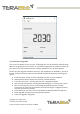
3.1 Graphical User Interface (version 1.0.3) A free Graphical User Interface (GUI) is available, providing an easy way to visualize the data from your TeraRanger Evo. This is useful for demonstration, testing purposes and checking some of the basic parameters of the sensor. It also provides a way to easily upgrade the firmware running on the device. The GUI is available for download here: GUI Download. (See “Download” section of the TeraRanger Evo product page).
3.1.3 Firmware Upgrade The current firmware version on your TeraRanger Evo can be found by selecting H elp > About in the graphical user interface. It is possible to upgrade the firmware running on your device if a new firmware version is made available on the Terabee website. Please note the Upgrade Firmware feature is only supported on Windows 7, 8 and 10. Please carefully follow the steps outlined below to avoid permanently disabling your device.
3.2 Connecting the TeraRanger Evo to a Host Computer TeraRanger Evo can interact as a virtual COM port using the following configuration: 115200 bit/s, 8 data bits, no parity bit and one stop bit. In Windows you can also use any terminal emulation software of your choosing, however we suggest you use HTerm (http://www.der-hammer.info/terminal/). Extract the downloaded zip file to the folder of your choice, open it and double click on the “HTerm.exe” document.
To communicate with the terminal emulation software, you need to send a command in hexadecimal via the “Type” box. First check the “Hex” checkbox and choose the “HEX” Type. The figure above shows an example of the command which allows data to be shown in TEXT mode. 4 I2C/UART backboard use 4.2 I2C/UART interface The TeraRanger Evo can be controlled through I2C o r UART interfaces. It uses a single 9 pin Hirose DF13 connector for interfacing to the host system.
5 SCL I2C serial clock line. 3.3V logic 6 rfu RESERVED FOR FUTURE USE 7 5V +5V supply input 8 GND Power supply and interface ground 9 rfu RESERVED FOR FUTURE USE 4.2.1 Backboard LEDs Five LEDs are mounted to give visual feedback on the sensor. Table 2 lists the functionality of each LED: LED Description PWR (orange) Power indicator, on when 5V connected Rx/Tx (red/green) UART receive and transmit indicators LED 0 / LED 1 For internal use only 4.2.
consumption (mA) Evo 15m 90 mA 330 mA Evo 3m 4.75 V 70 mA 5.25 V 250 mA (referenced to +3V3) - 1 LOW 2.3 - Interface logic levels HIGH * Value recorded while reading a target at 2m distance. NB: this value depends on ambient conditions, distance and target reflectivity 4.
**The TeraRanger Evo will output 01CRC (first distance byte set to zero and the second to one) as an error message i f the sensor is unable to measure a distance. If the target is too close (below the minimum distance), the TeraRanger Evo will output 00CRC (both distance bytes set to zero). If the target is too far away (above the maximum distance), the TeraRanger Evo will output XXCRC with XX = FFFFhex (both distance bytes set to 0xFF) Writing commands to the TeraRanger Evo: 1.
Wait at least 1 second for the TeraRanger Evo to rejoin the I2C bus with the new address. 1] This command assigns a base address that will be memorised by the TerRanger Evo ie. power cycling the Evo will not restore the default I2C address. [2] V alid addresses accepted by the TeraRanger Evo are in the range 0x02 to 0x7F. Assignment of addresses within a local system is up to the system architect.
0x00 PRINTOUT MODE 0x11 BINARY 0x4C 0x02 The default mode of TeraRanger Evo is Binary mode. For changing the output format to Text mode, please use the following command in hexadecimal: 0 0 11 01 45. Accordingly, to switch back to Binary mode use the hexadecimal command: 0 0 11 02 4C. 4.4.3 UART output format Two output formats are available: Text output Data output in human readable form (5 to 7 bytes message): xxxxx\n - Distance reading in millimeters* (maximum 5 bytes per sensor): xxxxx
- If the target is too far away (above the maximum distance), the TeraRanger Evo will output TXXCRC with XX = FFFFhex (both distance bytes set to 0xFF) Copyright © Terabee 2021 Terabee, 90 Rue Henri Fabre 01630, St Genis-Pouilly, France (next to CERN) 15/17
5 Declaration of Conformity CE certified, eye-safe and RoHS compliant Copyright © Terabee 2021 Terabee, 90 Rue Henri Fabre 01630, St Genis-Pouilly, France (next to CERN) 16/17
Copyright © Terabee 2021 Terabee, 90 Rue Henri Fabre 01630, St Genis-Pouilly, France (next to CERN) 17/17