
TeraRanger Evo 60m I2C ToF Distance Sensor User Manual

1Introduction
The purpose of this document is to give guidelines for use and integration of the TeraRanger
Evo 60m and TeraRanger Evo 600Hz distance sensors with (a) UART/I2C backboard,
and/or (b) USB backboard using these standard communication interfaces.
2Mechanical integration
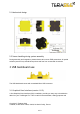
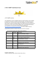
The mechanical design of the main sensor module (black) allows easy assembly to its
backboard (yellow) using a simple ‘clip-in’ technique. (When you clip the two together,
ensure there is no visible gap between the black and yellow parts.) The yellow backboard
has two mounting holes for final installation. A yellow sticker is applied on TeraRanger Evo
600Hz to differentiate it from TeraRanger Evo 60m.
When choosing a place for mounting, please consider the following recommendations:
● Choose a place which is in accordance with the optical constraints listed below
● Mounting close to sources of heat or strong electromagnetic fields can decrease the
sensing performance
● Do not mount anything directly in front of the sensor or in a cone of approximately
+/-15° around the central optical axis of the sensor
● Within the first meter from the sensor, avoid objects with high surface reflectivity in a
cone of approximately +/-45° around the central optical axis of the sensor
● It is better to avoid having other sources of Continuous Wave or modulated IR light
close to the sensor
● Please consider that dust, dirt and condensation can affect the sensor performance
● It is not advised to add an additional cover in front of the sensor
● Drone rotor blades, or other environments with flickering (‘chopped’) ambient light in
the field of view can affect sensors’ readings
Copyright © Terabee 2018
Terabee, 90 Rue Henri Fabre, 01630, St Genis-Pouilly, France
3/13