Installation Instructions TWSD16128PHC-UL Version 1.1 - Page 1 10521 Gulfdale, San Antonio, TX 78216 I www.terrawave.com I Email: sales@terrawave.
Introduction The TWSD16128PHC-UL is intended to be used with UL listed WLAN / Networking devices both indoors and outdoors and to provide NEMA 3R protection with cooling and heating. Maximum internal ambient temperature is 45 Degrees Celsius. Before installing this product, read these instructions carefully. Failure to follow these instructions could lead to damage to the product or cause hazardous conditions.
Do not use liquid cleaners or aerosol cleaners. Use a damp cloth for cleaning. Mount the unit according to these instructions only using the recommended or supplied hardware. Wear proper eye protection when using power and hand tools. Follow all safety instructions provided with the tools. This unit should only be connected to the type of power source indicated. If you are unsure of the type of power supply, consult the local power company.
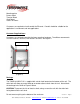
Installation Instructions Installation Environment The TWSD16128PHC-UL is intended for both indoor and outdoor use. Maximum internal ambient is 45 Degrees Celsius. Always mount the enclosure with the drain hole facing down (figure 1). Failure to do so could cause the unit to fill with water; creating hazardous conditions and equipment damage.
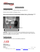
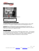
Mounting plate Power socket Terminal Block Cord Gland Cable Tie Downs Customers are required to install conduit for Ethernet. Conduit should be suitable for the application’s environment and wet applications. Customer Supplied Items Customers are required to provide their own mounting hardware. TerraWave recommends 3/8 inch fasteners, washers, lock washers and nuts. See figure 2.
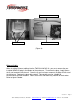
(Figure 3) Drain hole on bottom of enclosure. Do not mount anything on the bottom of the enclosure. Installing WLAN / Networking Components The TWSD16128PHC-UL will accommodate WLAN / Networking products to be installed inside the unit. This equipment should be installed on the mounting plate in the unit. WARNING: Water or condensation may build up on the bottom of the enclosure. No equipment or live parts should be installed or placed on the bottom surface of the enclosure.
Coaxial cable tie down Cable tie downs Ethernet cable tie down (Figure 4) Ethernet Cable When installing Ethernet cabling into the TWSD16128PHC-UL, you must remove the preinstalled NEMA 3R plug in the bottom of the enclosure. To remove the plug, simply loosen the fly nut located inside the unit. Once the fly nut has been removed, the plug will fall out of the enclosure. Replace the plug with conduit. The conduit must be suitable for environmental and wet locations.
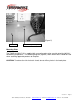
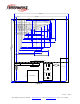
(Figure 5) Drain Hole NEMA 4 Plug with Fly Nut Mounting Plate The TWSD16128PHC-UL is supplied with a mounting plate to be used for attaching WLAN / Networking components. The following diagram (figure 6) shows which holes should be used when attaching approved products to the plate. CAUTION: To reduce the risk of electric shock, do not drill any holes in the back plate. Version 1.1 - Page 8 10521 Gulfdale, San Antonio, TX 78216 I www.terrawave.com I Email: sales@terrawave.
10.875" 10.563" 0.313 8.25" B B 3.50" A 8.187" 7.437" 5.937" 3.125" 3.875" 3.375" 4.125" 5.875" 4.625" 5.75" 6.875" 3.687" 6.375" 7.062" 6.625" 2.50" 0.313" 0.25" A 5.437" 4.937" 3.437" 3.375" 3.00" A 3.312" 2.687" A D 3.938" J D C D H C 12.563" E B J B J D A A G 4.063" 2.875" Nothing higher than 4" from bottom Heater Terminal Block Wires Out Fan Space Wires In 12.875" F H I 6.50" I J A A (Figure 6) Version 1.
Hole Size Chart Hole A B, C, D, I, J E, F, G H = = = = Size & Thread 7/32” through hole – not threaded 8-32 threaded hole 10-32 threaded hole 6-32 threaded hole Hole usage ledger Used for Mounting holes to mate up with 10-32 thread x 2” standoffs Cisco 350 Metal Case Cisco 340 & 350 Plastic Case (F is for 10-32 locking post) Cisco 1200 and 3Com 8250 Proxim AP (I is for 10-32 locking post) Cisco 1130 AP Symbol 4131 (G is for 10-32 locking post) Hole A B C&F D I&E J H&G Customer Provided WLAN/Networking
Attachment Attach the enclosure to a wall or other structure using the customer supplied 3/8 inch fasteners, flat washers and nuts. To ensure that the unit maintains proper sealing, it is very important to be sure that the fasteners, washer and nuts are tightened thoroughly. Note: Loose fasteners, washers and nuts may not provide proper sealing and /or securing of the unit.
The strain relief (liquid tight cord connector) is suitable for flexible cord with a diameter of 10mm. We recommend using S-W or S-J cord, minimum 16 AWG. WARNING: TO REDUCE THE RISK OF ELECTRIC SHOCK, DISCONNECT SUPPLY MAINS BEFORE SERVICING. The supply line used to feed power to the feeder circuit should be rated for outdoor use. Refer to the NEC and local codes as applicable.
(Figure 8) Strain relief bushing on outside of enclosure. When installing the strain relief, be sure that the gasket (black) is on the outside of the enclosure. Strain relief bushing nut on inside of enclosure. DO NOT OVER TIGHTEN! Version 1.1 - Page 13 10521 Gulfdale, San Antonio, TX 78216 I www.terrawave.com I Email: sales@terrawave.
Running Power to the Unit Legend H – Hot lead GND – Ground N – Neutral (Figure 9) Note that all cables need to be rated for outdoor use and wet environments. Refer to the NEC and local codes as applicable. Figure 5 represents the terminal block and power leads that are wired to the terminal block inside the TWSD16128PHC-UL. The wiring should be applied as follows: 1.) The Black wire in figure 5 represents the hot lead and should be attached to the terminal block that is labeled ‘H’. 2.