63 Digital Multimeter Instruction Manual
TABLE OF CONTENTS A. INTRODUCTION page A. INTRODUCTION 1. Congratulations . . . . . . . . . . . . . . . . . .3 2. Product Description . . . . . . . . . . . . . .3 3. EC Declaration of Conformity . . . . . . . .4 1. Congratulations!! B. SAFETY CONSIDERATIONS . . . . . . . . . . . .5 2. Product Description C. TECHNICAL DATA 1. Features and Benefits . . . . . . . . . . . . .6 2. Product Applications . . . . . . . . . . . . . .7 2. Specifications . . . . . . . . . . . . . . . . . . .8 D.
TABLE OF CONTENTS A. INTRODUCTION page A. INTRODUCTION 1. Congratulations . . . . . . . . . . . . . . . . . .3 2. Product Description . . . . . . . . . . . . . .3 3. EC Declaration of Conformity . . . . . . . .4 1. Congratulations!! B. SAFETY CONSIDERATIONS . . . . . . . . . . . .5 2. Product Description C. TECHNICAL DATA 1. Features and Benefits . . . . . . . . . . . . .6 2. Product Applications . . . . . . . . . . . . . .7 2. Specifications . . . . . . . . . . . . . . . . . . .8 D.
3.
3.
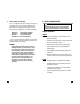
INTERNATIONAL SYMBOLS CAUTION: RISK OF ELECTRIC SHOCK AC (ALTERNATING CURRENT) DC (DIRECT CURRENT) Perform the following tests and/or measurements with the TPI 163 and the appropriate function: HVAC/R REFER TO INSTRUCTION MANUAL FUNCTION DCmV GROUND ACA • Heat anticipator current in thermostats. FUSE ACV • Line voltage. DOUBLE INSULATION ACV or DCV • Control circuit voltage. DCµA • Flame safeguard control current. OHMS • Heating element resistance (continuity).
INTERNATIONAL SYMBOLS CAUTION: RISK OF ELECTRIC SHOCK AC (ALTERNATING CURRENT) DC (DIRECT CURRENT) Perform the following tests and/or measurements with the TPI 163 and the appropriate function: HVAC/R REFER TO INSTRUCTION MANUAL FUNCTION DCmV GROUND ACA • Heat anticipator current in thermostats. FUSE ACV • Line voltage. DOUBLE INSULATION ACV or DCV • Control circuit voltage. DCµA • Flame safeguard control current. OHMS • Heating element resistance (continuity).
3. Specifications IEC 1010 Over Voltage: CAT II - 1000V CAT III - 600V Pollution Degree 2 UL 3111-1 Fuse* (fast blow) 3260mA 0.001mA 32.6mA 0.01mA 326mA 0.1mA 10A 0.01A a. DCV Range Resolution Accuracy Impedance 326mV 3.26V 32.60V 326V 1000V 0.1mV 0.001V 0.01V 0.1V 1V ±0.5% of reading, ±2 digits ±1.0% of reading, ±2 digits 10MΩ b. ACV Range Resolution Accuracy Impedance 3.26V 32.6V 326V 750V 0.001V 0.01V 0.1V 1V ±1.
3. Specifications IEC 1010 Over Voltage: CAT II - 1000V CAT III - 600V Pollution Degree 2 UL 3111-1 Fuse* (fast blow) 3260mA 0.001mA 32.6mA 0.01mA 326mA 0.1mA 10A 0.01A a. DCV Range Resolution Accuracy Impedance 326mV 3.26V 32.60V 326V 1000V 0.1mV 0.001V 0.01V 0.1V 1V ±0.5% of reading, ±2 digits ±1.0% of reading, ±2 digits 10MΩ b. ACV Range Resolution Accuracy Impedance 3.26V 32.6V 326V 750V 0.001V 0.01V 0.1V 1V ±1.
Fuse Protection Display Type mA: 0.5Amp/600VAC A: 10Amp/600VAC 3260 Count,with 34 segment bargraph and low battery indication. -0° to 40°C (32° to 104°F) -10° to 50°C (14° to 122°F) 0% to 80% 2 each 1.5 Volt “AA” Batteries 200 hrs. Typical 33mm x 86mm x 187mm (1.3in x 3.4in x 7.4in) 340g (12oz) Operating Temp. Storage Temp. Relative Humidity Power Supply Battery Life Size (H x L x W) Weight D. MEASUREMENT TECHNIQUES 1. Controls and Functions: mA Function for measuring milliamps (mA) AC. 1 milliamp = 0.
Fuse Protection Display Type mA: 0.5Amp/600VAC A: 10Amp/600VAC 3260 Count,with 34 segment bargraph and low battery indication. -0° to 40°C (32° to 104°F) -10° to 50°C (14° to 122°F) 0% to 80% 2 each 1.5 Volt “AA” Batteries 200 hrs. Typical 33mm x 86mm x 187mm (1.3in x 3.4in x 7.4in) 340g (12oz) Operating Temp. Storage Temp. Relative Humidity Power Supply Battery Life Size (H x L x W) Weight D. MEASUREMENT TECHNIQUES 1. Controls and Functions: mA Function for measuring milliamps (mA) AC. 1 milliamp = 0.
A Red test lead connection for current measurements on the 10A functions. mAµA Red test lead connection for current measurement on the mA and µA functions. COM Black test lead connection for all functions. VΩ Red test lead connection for all Volt, Ohm, Diode and Continuity measurements. a. MEASURING DC VOLTS (cont.) Application Notes 2. Step by Step Procedures: a. MEASURING DC VOLTS CAUTION! Do not attempt to make a voltage measurement if a test lead is plugged in the A or µmA input jack.
A Red test lead connection for current measurements on the 10A functions. mAµA Red test lead connection for current measurement on the mA and µA functions. COM Black test lead connection for all functions. VΩ Red test lead connection for all Volt, Ohm, Diode and Continuity measurements. a. MEASURING DC VOLTS (cont.) Application Notes 2. Step by Step Procedures: a. MEASURING DC VOLTS CAUTION! Do not attempt to make a voltage measurement if a test lead is plugged in the A or µmA input jack.
Measurement Procedure: 1. Disconnect power to the circuit to be measured. 2. Plug the black test lead into the COM input jack. 3 Plug red test lead into the VΩ 4. Set rotary switch to the V range. input jack. 5. Connect the test leads to the circuit to be measured. Application Notes Disconnect power from the terminal block, find the fuse or circuit breaker that controls the block and turn it off. Set up the meter following the steps under “Measurement Procedure” on page 15.
Measurement Procedure: 1. Disconnect power to the circuit to be measured. 2. Plug the black test lead into the COM input jack. 3 Plug red test lead into the VΩ 4. Set rotary switch to the V range. input jack. 5. Connect the test leads to the circuit to be measured. Application Notes Disconnect power from the terminal block, find the fuse or circuit breaker that controls the block and turn it off. Set up the meter following the steps under “Measurement Procedure” on page 15.
Measurement Procedure: FUNCTION BLACK TEST LEAD 1. Disconnect power to the circuit to be measured. 2. Plug the black test lead into the COM input jack. 3. Plug the red test lead into the VΩ 4. RED TEST LEAD MINIMUM READING MAXIMUM READING µA COM mAµA 0.1µA 3260µA mA COM mAµA 0.01mA 326mA 10A COM A 0.01A 10.00A input jack. Set the rotary switch to the V function. 5. Connect the test leads to the circuit to be measured. 6. Reconnect power to the circuit to be measured. 7.
Measurement Procedure: FUNCTION BLACK TEST LEAD 1. Disconnect power to the circuit to be measured. 2. Plug the black test lead into the COM input jack. 3. Plug the red test lead into the VΩ 4. RED TEST LEAD MINIMUM READING MAXIMUM READING µA COM mAµA 0.1µA 3260µA mA COM mAµA 0.01mA 326mA 10A COM A 0.01A 10.00A input jack. Set the rotary switch to the V function. 5. Connect the test leads to the circuit to be measured. 6. Reconnect power to the circuit to be measured. 7.
TEST LEAD TEST LEAD READING READING COM mAµA 0.1µA 3260µA mA COM mAµA 0.01mA 326mA 10A COM A 0.01A 10.00A µA Measurement Procedure: Application Notes When measuring resistance of a motor, make sure the power is disconnected prior to testing.
TEST LEAD TEST LEAD READING READING COM mAµA 0.1µA 3260µA mA COM mAµA 0.01mA 326mA 10A COM A 0.01A 10.00A µA Measurement Procedure: Application Notes When measuring resistance of a motor, make sure the power is disconnected prior to testing.
4. Instrument set-up: FUNCTION BLACK TEST LEAD RED TEST LEAD MINIMUM READING MAXIMUM READING Ω VΩ 0.1Ω 32.6M COM Measurement Procedure: f. 1. Disconnect power to the circuit to be measured. 2. Plug the black test lead into the COM input jack. 3. Plug the red test lead into the VΩ 4. Set the rotary switch on the 163 to the Ω function. 5. Connect the test leads to the circuit to be measured. 6. Read the resistance value on the 163. input jack. Set the rotary switch to the 5.
4. Instrument set-up: FUNCTION BLACK TEST LEAD RED TEST LEAD MINIMUM READING MAXIMUM READING Ω VΩ 0.1Ω 32.6M COM Measurement Procedure: f. 1. Disconnect power to the circuit to be measured. 2. Plug the black test lead into the COM input jack. 3. Plug the red test lead into the VΩ 4. Set the rotary switch on the 163 to the Ω function. 5. Connect the test leads to the circuit to be measured. 6. Read the resistance value on the 163. input jack. Set the rotary switch to the 5.
3. Plug the red test lead into the VΩ input jack. Standard Accessories Part No. 2 Each 1.5 Volt “AA” Batteries Fuse, 0.5 Amp Fuse, 10 Amp Test Lead Set Rubber Boot A002 A104 A110 A050 A101 Optional Accessories Part No. Deluxe Test Lead Set IEC 1010 Deluxe Test Lead Kit Temperature Adapter Boot Hook Soft Carrying Case SDK1C TLS2000BC A301 A103 A100 *These accessories have not been evaluated by UL and are not considered as part of the UL Listing of this product. 4.
3. Plug the red test lead into the VΩ input jack. Standard Accessories Part No. 2 Each 1.5 Volt “AA” Batteries Fuse, 0.5 Amp Fuse, 10 Amp Test Lead Set Rubber Boot A002 A104 A110 A050 A101 Optional Accessories Part No. Deluxe Test Lead Set IEC 1010 Deluxe Test Lead Kit Temperature Adapter Boot Hook Soft Carrying Case SDK1C TLS2000BC A301 A103 A100 *These accessories have not been evaluated by UL and are not considered as part of the UL Listing of this product. 4.
163 SPECIFICATIONS ±0.5% Basic DCV Accuracy (also see pages 8-9) Function Range Resolution DCV 326mV 3.26V 32.6V 326V 1000V 0.1mV 0.001V 0.01V 0.1V 1V ACV 3.26V 32.6V 326V 750V 0.001V 0.01V 0.1V 1V DCA 326µA 3260mA 32.6mA 326mA 10A 0.1µA 0.001mA 0.01mA 0.1mA 0.01A ACA 326µA 3260µA 32.6mA 326mA 10A 0.1µA 1µA 0.01mA 0.1mA 0.01A OHM 326Ω 3.26kΩ 32.6kΩ 326kΩ 3.26MΩ 32.6MΩ 0.1Ω 0.001kΩ 0.01kΩ 0.1kΩ 0.001MΩ 0.01MΩ Test Voltage Max. Test Current Diode 3V Approx. 0.