
Instruction Manual


31
30
31
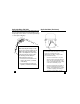
When measuring resistance of a motor, make
sure the power is disconnected prior to testing.
Set up meter following steps under
“Measurement Procedure” on page 16, and
proceed with the following:
• Connect the red test lead to one power
input line of the motor and the black test
lead to the other power input line of the
motor. In most applications if the reading
is OFL, the motor winding is open.
• Connect the red test lead to the frame of
the motor and the black test lead to the
winding. In most applications if a reading
of 0 Ohms is displayed, the winding is
shorted to the motor frame (ground).
Application Notes (DC Volts)
The 270 will accurately measure rectified DC Voltages like
those encountered in furnaces and other appliances even
though many of these devices do not have output filtering
or other signal conditioning.
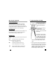
When measuring DC Voltage of a bat-
tery, the most accurate reading can be
attained by testing the battery under
load. To accomplish this, follow steps
1 through 4 shown on page 14 and
the following (with the battery in
holder and device turned on):
• Connect the red test lead from the
meter to the positive (+) terminal
of the battery.
• Connect the black test lead to the
negative (-) terminal of the battery.
Application Notes (Resistance)