LanScaper OPERATING INSTRUCTIONS TM
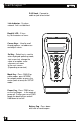
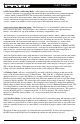
LanScaper TM RJ45 Jack - Connect to cable or jack to be tested. Link Indicator - On when network link is established. Back-lit LCD - 2 lines by 16 characters w/ icons. Curser Keys - Used to scroll through options, set addresses and adjust values. Sel Key - Select key is used to enter displayed operating mode, start a new test, change the value of an option, enter sub-menus or move to the next screen.
LanScaper TM 1.0 INTRODUCTION 1.1 Cautions 1.2 Kit Contents 1.3 Features 1.4 Using this Manual 1.5 Network Connectivity Page 3 3 3 3 3 4 2.0 STEP BY STEP USE INSTRUCTIONS 2.1 To ID an Unknown Jack or Plug 2.2 To Test Cables Only 2.3 To Place Tone on a Cable 2.4 To Measure Length of a Cable 2.5 To Locate an Ethernet Port 2.6 To PING Devices on a Network 2.7 To Validate a Cable Link by Functional Testing 2.8 To Change PING Addressing Mode 4 4 4 4 4 5 5 5 6 3.0 FUNCTIONAL DESCRIPTION 3.1 Voltage Check 3.
LanScaper TM For detailed description of each function, see the Functional Description section. Interpreting Cable Test Results and Error Messages sections are useful reference sections. 1.5 Network Connectivity - The LanScaper™ uses IP address protocol and recognizes AutoNegotiation using Fast Link Pulses to report advertised Ethernet capability. LanScaper™ also supports a modified version of auto MDI/MDI-X to allow for connection to a HUB, switch or NIC with a straight through cable.
LanScaper TM 3) Press up/down arrows to adjust length constant. If length constant is unknown for a particular cable, a known length of cable may be used to set the constant. Fifty feet or more is suggested to minimize the resolution error (1 foot in 50 is 2% uncertainty). Connect known cable to tester and change the cable constant using up/down arrows until the length reads correctly. 2.
LanScaper TM 2.8 To Change PING Addressing Mode - Other options are changed similarly. 1) Turn on LanScaper™ by pressing PWR button and press the middle of the CABLE/NTWRK button, which is marked SETUP. The percent battery remaining screen will appear briefly. 2) Press down arrow button three times, DHCP On or DHCP Off should be displayed. 3) Press SEL button to toggle between on and off. Displayed value is current setting. 4) Press CABLE or NTWRK to exit to a test or press and hold PWR button to power off.
LanScaper TM 3.2.1 Jack ID - The Jack ID test identifies what equipment, if any is, connected to the other end of the jack or cable being tested. The test first looks for voltages being present on the connector pins. If voltages are found in typical phone locations, tests for current levels and dial tone are run. From these tests, the LanScaper™ will report voltage or phone type found. If no voltages are present, testing for Ethernet link pulses commences.
LanScaper TM 3.2.4 Tone Generator - The tone mode generates audio tones for use with tone tracers on all pairs, a selected pair or a selected pin. The signal generated on a pair has the signal on one pin and the complement of the signal on the other pin of the pair, yielding a nominal 10 volts peak-to-peak across the pair. The SEL button selects one of the four tone sounds provided. The up/down arrows scroll through the pairs and pins that have signal on them.
LanScaper TM (ARP) request directed to its proposed MyIP address. A response to the ARP tells the tester that some other device on the LAN is already using that IP address. The DHCP protocol specification (RFC 1541) says that in the case a server offers an address already in use, the receiver of that address should reject it and request another. The LanScaper™ does not inform the server about the conflict, but it does report on the LCD “My IP in use on this network”.
LanScaper TM The tester sends out an ARP packet directed to the Router, and needs a response from the Router informing the tester of the Router's MAC address. During this phase, “ARP” will flash under the “Rtr” acronym. If no response is received to the ARP request, the tester will repeat the request at varying intervals (1-3 seconds).
LanScaper TM 3.3.3 Validate Link - This mode allows two LanScaper™ testers to be connected directly to each other on a cable with no other equipment required. No special configuration of the testers is required other than to put them into the test modes as described. This allows a cable run to be verified after installation. One LanScaper™ is put into Validate Link mode (Validator), while the other one is put into PING test with DHCP Off (PING Generator).
LanScaper TM Each of the four decimal numbers separated by periods represents one hexadecimal byte of the four byte IP address, and can only take on the values between 0-255. Each digit in the decimal number can only be set to a value valid for that position. Thus, the high order digit in any of the decimal numbers can only be set to 0, 1, or 2. In addition, each digit can only be set to a valid value in relation to the low-order digits in that number.
LanScaper TM 4.4 DHCP On/Off - This is a simple on-off selection made using the SEL button. The last displayed state is the selected state. DHCP is a protocol negotiation used to automatically configure the IP parameters of the LanScaper™ on a specific LAN segment. With DHCP On, the next time the PING test is started, the tester will request IP parameters it needs for LAN communication from a DHCP server on that LAN segment.
LanScaper TM NIC init err - The Ethernet interface chip used in the LanScaper™ reported a problem to the CPU during internal initialization. May be caused by a hardware problem inside the tester. NIC Rx overrun - The Ethernet interface chip used in the LanScaper™ provides internal buffering for multiple packets. If new packets are received faster than they can be processed, the Ethernet chip discards the new packets and sets the Overrun error flag. The tester detects and reports this error.
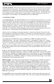
LanScaper TM 6.0 INTERPETING CABLE TEST RESULTS - The PASS icon will be on if the cable has all pins properly connected per T568A/B. Neither icon will be on if the cable is cross-over (uplink) cable. The FAIL icon will be on if there is any other condition. See Figure 6.1, Examples of Wiring Errors. Definition of Errors - The three classes of faults discussed below are in order of severity. The severity has to do with the ability of a more severe error to mask lower severity errors.
LanScaper TM Fig. 6.
LanScaper TM 7.0 MAINTENANCE 7.1 Battery Replacement - When the battery low icon is on, the battery should be replaced as soon as practical. The testing results will become unreliable when the battery reaches about 5.0 volts. To replace the battery: 1) Be sure tester is off. 2) Remove rubber battery cap by pressing on edge of the cap with the heel of the hand until the cap pops off. 3) Pull battery out of cavity and remove battery snap.
LanScaper TM Appendix A: Glossary of Networking Terms 10 Base-T - The earliest definition of Ethernet was for 10 Million Bits per second, 10 Mbps. The Ethernet specification defined several different cabling schemes, including T568A/B (4-pairs of wire) and coax wiring. The 10 in 10 Base-T defines 10 Mbps and the Base-T defines T568A/B, CAT3 cabling. 10 Base-2 defines 10 Mbps over coax. Note that the LanScaper™ PING mode works in 10 Base-T.
LanScaper TM NIC = Network Interface Card - Typically an option card plugged into a PC card slot that provides an Ethernet interface for that PC. LanScaper™ uses the term NIC to define the connector pin out that allows for direct connection to a HUB device using a straight-through cable. Polarity - Ethernet transmit and receive driver chips use differential voltages to improve noise immunity.
LanScaper TM Appendix B: Internet Protocol Definitions ARP = Address Resolution Protocol - Used to determine Ethernet (MAC) address when a device starts to communicate with another. The IP address is known and a broadcast is used to request the specific IP addressed device to respond with its MAC address, so further communication can be specifically addressed between the two.
LanScaper TM PING = Packet INternet Groper - A simple communication protocol (ICMP Echo) used to request an echo back from an addressed device (target). The LanScaper™ uses this to verify IP connectivity between itself and another device. Router = Gateway - If a device is attempting to communicate with an IP address, and it finds that the target is not on its local network (by comparing the target address with it's own address and the Netmask) the device must forward it's request to a router.
LanScaper TM WARRANTY - Test-Um Inc. guarantees to the end-user purchaser that its products will be free of all defects in material and/or workmanship. This warranty extends for a period of 12 months for the test instrument and 3 months for the cables from the date of manufacture or proof-of-purchase. The obligations of Test-Um Inc.
Test-Um Inc. The Intelligent Test Solutions Company 805-383-1500 / FAX 805-383-1595 / www.test-um.com 808 Calle Plano / Camarillo, CA.