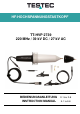
HF-HOCHSPANNUNGSTASTKOPF TT-HVP 2739 220 MHz / 39 kV DC / 27 kV AC BEDIENUNGSANLEITUNG INSTRUCTION MANUAL D-1 bis D-8 E-1 to E-8
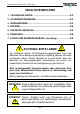
HF-Hochspannungstastkopf TT-HVP 2739 INHALTSVERZEICHNIS 1. TECHNISCHE DATEN .............................................................D-2 2. SICHERHEITSHINWEISE .........................................................D-3 3. WARNHINWEISE ......................................................................D-4 4. BETRIEB ...................................................................................D-5 5. TASTKOPF-ABGLEICH ............................................................D-6 6. REINIGUNG.
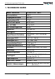
HF-Hochspannungstastkopf TT-HVP 2739 1. TECHNISCHE DATEN Modell / Bestell-Nr. TT-HVP 2739 / 15014 Teilerverhältnis 1000:1 Eingangswiderstand 900 MΩ Eingangskapazität 1,0 pF Max. DC+AC Spitze 39 kV CAT I Max. AC RMS 27 kV CAT I Max.
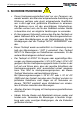
HF-Hochspannungstastkopf TT-HVP 2739 2. SICHERHEITSHINWEISE • Dieser Hochspannungstastkopf darf nur von Personen verwendet werden, die über eine entsprechende Ausbildung und Erfahrung verfügen oder durch entsprechende Qualifikationen in der Lage sind, gefährliche Situationen zu erkennen. Der Bediener muss mit den einschlägigen Sicherheitsvorschriften vertraut sein, die für den Gebrauch solcher Geräte zu beachten sind, um mögliche Verletzungen zu vermeiden.
HF-Hochspannungstastkopf TT-HVP 2739 • Den Tastkopfkörper stets sauber und frei von leitenden Verunreinigungen halten (siehe Abschnitt „Reinigung“). • Der Tastkopf darf nur in Innenräumen verwendet werden. • Vor dem Anschließen oder Abklemmen des Tastkopfes bitte unbedingt die Hochspannungsquelle abschalten. 3. WARNHINWEISE • Der Anschluss der Masseleitung ist Grundvoraussetzung für einen sicheren Betrieb des Tastkopfes.
HF-Hochspannungstastkopf TT-HVP 2739 Führen Sie mit diesem Hochspannungs-Tastkopf TT-HVP 2739 NIEMALS erdfreie Messungen durch! 3. BETRIEB 1. Verbinden Sie die Masseleitung des Tastkopfes (Krokodilklemme) mit einer guten Erdung oder zuverlässigen Gehäuseerde. 2. Schließen Sie den BNC-Stecker an den BNC-Eingang Ihres Oszilloskops an. 3. Wählen Sie den gewünschten Bereich Ihres Oszilloskops. Bevor Sie Anschlüsse vornehmen, schalten Sie die Hochspannungsquelle ab, wann immer dies möglich ist.
HF-Hochspannungstastkopf TT-HVP 2739 4. TASTKOPF-ABGLEICH Die folgende Einstellung ist immer erforderlich, wenn der Tastkopf auf ein anderes Oszilloskop oder einen anderen Eingangskanal abzugleichen ist. Schließen Sie den Tastkopf an das Oszilloskop an, legen Sie ein Rechtecksignal mit 200 Hz an die Tastkopfspitze an und stellen Sie das Oszilloskop so ein, dass einige Zyklen der Signalform angezeigt werden. Dann regeln Sie den Trimmer in Öffnung 1 auf das flachste Impulsdach ein.
HF-Hochspannungstastkopf TT-HVP 2739 WARNUNG – GEFAHR! (1) Die Einstellung über die Öffnungen 2 und 3 des Tastkopfes TT-HVP 2739 darf nur von qualifizierten Technikern vorgenommen werden. (2) Vor Einstellung über die Öffnungen 2 und 3 bitte zuerst die Kunststoffabdeckung abziehen. (3) Nur das mitgelieferte Abgleichwerkzeug verwenden.
HF-Hochspannungstastkopf TT-HVP 2739 6. REINIGUNG Den Tastkopf und die Kabel nur äußerlich mit einem weichen Baumwolltuch reinigen, das mit einer Lösung aus Wasser mit mildem Reinigungsmittel befeuchtet ist. Den Tastkopf oder Teile davon bitte nie in Wasser oder Flüssigkeiten tauchen. Trocknen Sie den Tastkopf gründlich ab, bevor Sie mit der Spannungsmessung beginnen. Den Tastkopf nie Lösungsmitteln oder Lösemitteldämpfen aussetzen, da diese zu Schäden am Gerätekörper und an den Kabeln führen können.
Weitere Hochspannungstastköpfe WEITERE HOCHSPANNUNGSTASTKÖPFE D-9
Weitere Hochspannungstastköpfe D-10
HIGH-FREQUENCY HIGH-VOLTAGE PROBE TT-HVP 2739 220 MHz / 39 kV DC / 27 kV AC INSTRUCTION MANUAL E-1 to E-8
HIGH-FREQUENCY HIGH-VOLTAGE PROBE
TT-HVP 2739 High-Frequency High Voltage Probe TABLE OF CONTENTS 1. SPECIFICATIONS ..................................................................... E-2 2. SAFETY PRECAUTIONS.......................................................... E-3 3. WARNINGS ............................................................................... E-4 4. OPERATION .............................................................................. E-5 5. COMPENSATION ADJUSTMENT ............................................ E-6 6.
TT-HVP 2739 High-Frequency High Voltage Probe 1. SPECIFICATIONS Model / Order-No. TT-HVP 2739 / 15014 Division Ratio 1000:1 Input Resistance 900MΩ Input Capacitance 1.0pF Max. DC+AC peak 39kV CAT I Max. AC RMS. 27kV CAT I Max. Loading Current 45µA Band Width DC ~ 220MHz Rise Time 1.6nS Signal / Noise >60dB @ 1KHz ; >50dB @ 1MHz DCV Accuracy ≦3% (0 ~ 35kV) ACV Accuracy ≦3% @ 1kHz Temp.
TT-HVP 2739 High-Frequency High Voltage Probe 2. SAFETY PRECAUTIONS • This high voltage probe must only be used by personnel who are trained, experienced, or otherwise qualified to recognize hazardous situations and who are trained in the safety precautions that are necessary to avoid possible injury when using such a device. • For your own safety, inspect the probes for cracks and frayed or broken leads before each use. If defects are noted, DO NOT USE the probe.
TT-HVP 2739 High-Frequency High Voltage Probe 3. WARNINGS • The ground lead is critical to the safe operation of the probe. Failure to make this connection when making high voltage measurements may result in personal injury or damage to the probe or oscilloscope. This connection must always be made BEFORE the probe tip comes in contact with the high voltage and must not be removed until the probe tip has been removed from the high voltage source.
TT-HVP 2739 High-Frequency High Voltage Probe 3. OPERATION 1. Connect the divider probe common lead (alligator clip) to a good earth ground or reliable ground. 2. Connect the BNC connector to the BNC input of your oscilloscope. 3. Select the desired range of your oscilloscope. Whenever possible, turn the high voltage source off before making any connections.
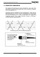
TT-HVP 2739 High-Frequency High Voltage Probe 4. COMPENSATION ADJUSTMENT The following adjustment is required whenever the probe is transferred from one oscilloscope or input channel to another. Connect the probe to the oscilloscope, apply a 200Hz square wave to the probe tip and adjust the oscilloscope controls to display a few cycles of the waveform. Adjust the trimmer located in the BNC plug for a flat topped square wave. Illustration of 200Hz square wave adjustment.
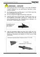
TT-HVP 2739 High-Frequency High Voltage Probe WARNING, RISK OF DANGER! (1) The TT-HVP 2739 adjustment holes 2 and 3 are for the qualified engineer only. (2) Before adjusting hole 2 and hole 3, please move off the plastic cover at first. (3) Use the supplied adjust bar only. (4) When the measured frequency is over 40MHz or to adjust the bandwidth (hole 3), you must use the short earth lead and connect it to the alligator clip to obtain the best frequency response.
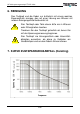
TT-HVP 2739 High-Frequency High Voltage Probe 6. CLEANING Clean only the exterior probe body and cables. Use a soft cotton cloth lightly moistened with a mild solution of detergent and water. Do not allow any portion of the probe to submerge at any time. Dry the probe thoroughly before attempting to make voltage measurement. Do not subject the probe to solvents or solvent fumes as these can case deterioration of the probe body and cables. 7. VOLTAGE DERATING CURVE ...........
MORE HIGH-VOLTAGE PROBES E-9
Testec Elektronik GmbH Fritz-Klatte-Str. 6 D - 65933 Frankfurt Germany Telephone: +49 (0) 69 - 94 333 5 - 0 Fax: +49 (0) 69 - 94 333 5 - 55 E-Mail: info@testec.de http://www.testec.