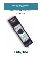
INSTRUCTION MANUAL TT-SI 7005 60MHz active differential probe x1 / x5 /x10
Safety Summary To avoid personal injury and/or product damage, review and comply with the following safety precautions. These precautions apply to both operating and maintenance personnel and must be followed during all phases of operation, service, and repair of this probe. A WARNING statement calls attention to an operating procedure, practice, or condition, which, if not followed correctly, could result in injury or death to personnel.
Not for Critical Applications This probe is not authorized for use in contact with the human body or for use as a component in a life-support device or system. Do Not Substitute Parts Do not install substitute parts or perform any unauthorized modification to the instrument. Only Qualified Personnel Only qualified personnel should use this probe.
Definitions Measurement Category II (CAT II) refers to local-level electrical distribution, such as that provided by a standard wall outlet or plug-connected equipment. Examples of CAT II measurements would be household appliances, portable tools, and similar modules. Measurement Category III (CAT III) refers to measurements on hard-wired equipment in fixed installations, distribution boards, and circuit breakers that form part of a building wiring installation.
1 Introduction Overview The TT-SI 7005 differential probe allows safe, accurate measurement between two voltage points where neither point is referenced to ground. The probe is designed for high sensitivity measurements up to 60 MHz bandwidth. Compatible with oscilloscopes from all major manufacturers, the probe is exclusively powered by the included 9 V power adapter.
Inspection Procedure 1. 2. 3. 4. Connect the BNC output connector to the vertical input of the oscilloscope. Power on the probe. Set the attenuation setting on the oscilloscope to match the probe. Connect the input of probe to a function generator. Then select a square-wave output of 10 V amplitude and 100 kHz frequency. 5. The square-wave will be displayed on the screen of the oscilloscope. This indicates the probe is working properly.
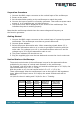
3 Product Overview Probe Input – 2 x 4mm Plug Over Range Indicator (Red) Attenuation Selector Switch Power Indicator (Red) External Power Supply Probe Output BNC Connector Included Accessories TT-SI NT7 Man_7005_1019 TT-SI TL7 TT-SI GR2 www.testec.
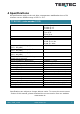
4 Specifications All specifications apply to the unit after a temperature stabilization time of 20 minutes over an ambient range of 25°C ± 5°C.
5 Voltage Derating Curve The derating curve of the absolute maximum input voltage in common mode is shown as follows: TT-SI 7005 Voltage Derating Figure: TT-SI 7005 Derating Curve 6 Cleaning This probe does not require any particular cleaning. If necessary, clean the case with a soft cloth. WARNING Dry the probe thoroughly before attempting to make voltage measurements.
7 Service & Warranty Information Limited One-Year Warranty Testec Elektronik GmbH warrants these products to be free from defective material or workmanship for a period of 1 year from the date of original purchase. Under this warranty, Testec Elektronik GmbH is limited to repairing the defective device when returned to the factory, shipping charges prepaid, within the warranty period.
TT-SI 7005 Differential Probe User’s Manual © 2019 TESTEC Elektronik GmbH. All rights reserved. Unauthorized duplication of TESTEC documentation materials is strictly prohibited. Customers are permitted to duplicate and distribute TESTEC documentations for internal educational purposes Man_700_0919 www.testec.