testo 550 · Digital manifold Instruction manual
1 Contents 1 Contents 1 Contents ...................................................................................................3 2 Safety and the environment....................................................................4 3 4 2.1. About this document ........................................................................4 2.2. Ensure safety...................................................................................5 2.3. Protecting the environment.............................
2 Safety and the environment 2 Safety and the environment 2.1. About this document Use > Please read this documentation through carefully and familiarize yourself with the product before putting it to use. Pay particular attention to the safety instructions and warning advice in order to prevent injuries and damage to the products. > Keep this document to hand so that you can refer to it when necessary. > Hand this documentation on to any subsequent users of the product.
2 Safety and the environment 2.2. Ensure safety > Do not operate the instrument if there are signs of damage at the housing, mains unit or feed lines. > Do not perform contact measurements on non-insulated, live parts. > Do not store the product together with solvents. Do not use any desiccants. > Carry out only the maintenance and repair work on this instrument that is described in the documentation. Follow the prescribed steps exactly. Use only original spare parts from Testo.
3 Specifications 3 Specifications 3.1. Use The testo 550 is a digital manifold for maintenance and servicing work at refrigeration systems and heat pumps. It must only be used by qualified authorized personnel. The testo 550 replaces mechanical manifolds, thermometers and pressure/temperature tables by means of its functions. Pressures and temperatures can be loaded, adjusted, tested and monitored. The testo 550 is compatible with most non-corrosive refrigerants, water and glycol.
3 Specifications Characteristic Values Accuracy (nominal temperature 22 °C/71.6 °F) Pressure: ±0.75 % of final value (±1 digit) No.
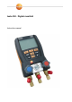
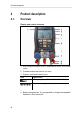
4 Product description 4 Product description 4.1. Overview Display and control elements 1 Mini-DIN probe socket for NTC temperature probe, with socket cover 2 Foldable suspension device (on rear) 3 Display. Instrument status icons: Icon Significance Battery capacity: >75 %/>50 %/>25 %/<10 % / / Select measuring mode (see) 4 Battery compartment.
5 First steps 5 Control keys: Key Function [Set] Set units [R, Start/ Stop] Select refrigerant/ Start/stop / Tightness test [Mode] Switching measuring mode [Min/Max/Mean] Display min./max.
5 First steps Switching the instrument on > Press [ ]. - Initialization phase: - Measurement view is opened. • All display segments are lit (length of time: 2 s). Performing settings 1. Press [Set]. - The configuration menu is opened and the adjustable parameter flashes. 2. Set parameters: Key functions Representation Explanation [▲] or [▼] Change parameter, select unit [Set] Select units/parameters Adjustable parameters Representation Explanation °C, °F Set temperature unit.
6 Using the product WARNING Only tighten valve positioner with your hand! Do not use any tools when tightening as otherwise the thread may be damaged. 6 Using the product 6.1. Preparing for measurement 6.1.1. Connecting the temperature sensor Sensors must be connected before the measuring instrument is switched on, so that they are recognised by the instrument.
6 Using the product 6.1.2. Switching the instrument on > Press [ ]. Zeroing the pressure sensors Zero the pressure sensors before every measurement. ✓ All connections must be pressureless (ambient pressure). > Press key [P=0] and execute zeroing. Connecting the refrigerant hoses Before each measurement check whether the refrigerant hoses are in flawless condition. ✓ The valve actuators are closed. 1.
6 Using the product Key functions Representation Explanation [▲] or [▼] Changing the refrigerant [R, Start/Stop] Confirm the setting and exit the refrigerant menu. Available refrigerants Representation Explanation R... Refrigerant number of refrigerant acc. to ISO 817 T... Special Testo designation for certain refrigerants (T8 = T1234yf) --- no refrigerant selected. Example: Setting refrigerant R401B 1. Press [▲] or [▼] several times, until R401B flashes. 2.
6 Using the product Display Mode Function display. This mode is especially suited to air conditioning systems which cool and heat. 6.2. Performing the measurement WARNING Risk of injury caused by refrigerant that is at high pressure, hot, cold, or poisonous! > Wear safety goggles and protective gloves.
6 Using the product - Reading and display illumination flash: • 1 bar before reaching the critical pressure of the refrigerant, • upon exceeding the max. permissible pressure of 50 bar. Key functions > [▲] or [▼]: Change the reading display.
7 Maintaining the product - Result is displayed. 4. Confirm message: Press [Mode]. - You automatically jump to the evacuation/vacuum display menu. Evacuation/vacuum display The measurement is performed on the low-pressure side. 5. Press [Mode]. - Result is displayed on the low-pressure side. 6. Press [Mode]. - 7 The measuring mode is displayed. Maintaining the product Cleaning the instrument > If the housing of the instrument is dirty, clean it with a damp cloth.
7 Maintaining the product Changing batteries/rechargeable batteries ✓ Instrument is switched off. 1. Fold out the suspension device, loosen the clip and remove the cover of the battery compartment. 2. Remove empty batteries/rechargeable batteries and insert new batteries/rechargeable batteries (4x 1.5 V, type AA, Mignon, LR6) in the battery compartment. Observe the polarity! 3. Set on and close cover of the battery compartment (clip must engage). 4. Switch the instrument on.
8 Tips and assistance 8 Tips and assistance 8.1. Questions and answers Question Possible causes/solution Batteries are almost empty. flashes > Change batteries. The instrument switches off automatically. Residual capacity of the batteries is too low. > Change batteries. uuuu lights up instead of the parameter display The permissible measuring range has been undershot. > Keep to the permitted measuring range.
8 Tips and assistance 8.3. Error reports Question Possible causes/solution ---- is lit up instead of measurement parameter display Sensor or cable defective Display EEP FAIL Eeprom defective > Please contact your dealer or Testo Customer Service > Please contact your dealer or Testo Customer Service 8.4. Accessories and spare parts Description Article no. Clamp probe for temperature measurement at pipes 0613 5505 Pipe wrap probe with Velcro tape for pipe diameters of up to max. 75 mm, Tmax.
FCC statements: This device complies with part 15 of the FCC rules. Operation is subject to the following two conditions: (1) this device may not cause harmful interference, and (2) this device must accept any interference received, including interference that may cause undesired operation. NOTE: The manufacturer is not responsible for any radio or TV interference caused by unauthorized modifications or changes to this equipment.