testo 875i · Thermal imager Instruction manual
1 Contents 1 Contents 1 Contents ...................................................................................................3 2 Safety and the environment ....................................................................4 2.1. About this document ........................................................................4 2.2. Ensure safety...................................................................................5 2.3. Protecting the environment .......................................
2 Safety and the environment 2 Safety and the environment 2.1. About this document Use > Please read this documentation through carefully and familiarize yourself with the product before putting it to use. Pay particular attention to the safety instructions and warning advice in order to prevent injuries and damage to the products. > Keep this document to hand so that you can refer to it when necessary. > Hand this documentation on to any subsequent users of the product.
2 Safety and the environment 2.2. Representation Explanation [OK] Control keys of the instrument or buttons of the program interface. ... | ... Functions/paths within a menu. “...” Example entries Ensure safety > Only operate the product properly, for its intended purpose and within the parameters specified in the technical data. Do not use any force. > Do not operate the instrument if there are signs of damage at the housing, mains unit or feed lines.
2 Safety and the environment • • • • 2.3. Only charge in the instrument or the recommended charging station. Immediately stop the charging process if this is not completed in the given time. In the event of improper function or signs of overheating, immediately remove the rechargeable battery from the measuring instrument/charging station. Caution: Rechargeable battery may be hot! During longer breaks, remove the battery from the instrument to avoid exhaustive discharge.
3 Specifications 3 Specifications 3.1. Use The testo 875i is a handy and robust thermal imager. It opens the door to contactless determination and illustration of the temperature distribution on surfaces for you.
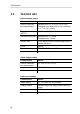
3 Specifications 3.2. Technical data Infrared image output Characteristic Values Field of vision/min. focusing distance Standard lens: 32° x 23°/0.1 m (0.33 ft) Telephoto lens (testo 875-2i only, optional): 9° x 7° / 0.5 m (1.64 ft) Thermal sensitivity (NETD) <50 mK at 30 °C (86 °F) Geometric resolution Standard lens: 3.3 mrad Telephoto lens: 1 mrad Refresh rate 33 Hz within EU and countries approved for export, else 9 Hz Focus Manual Detector type FPA 160 x 120 pixels, a.
3 Specifications Measuring Characteristic Values Temperature range (can be changed) Measuring range 1: -20 - 100 °C (-4 - 212 °F) Measuring range 2: 0 - 350 °C (32 - 662 °F) Measuring range 3 (optional, testo 875-2i only): 350 - 550 °C (662 - 1022 °F) Accuracy With measuring range 1 activated, for readings within the range of -20 - 100 °C (-4 - 212 °F): ±2 °C (±3.6 °F) With measuring range 2 activated, for readings within the range of 0 - 350 °C (32 - 662 °F): ±2 °C (±3.
3 Specifications Characteristic Values Measuring functions Standard measurement (1-point), 2-point measurement, Cold-/Hotspot, solar (manual entry of the radiation intensity) Also with testo 875-2i: isotherm, min./max. on area, Display of humidity image via manual entry of the ambient humidity / temperature (real-time display with optional radio humidity probe) Compensation for manual reflected temperature Setting emissivity 0.01…1.00 Image storage Characteristic Values File format .
3 Specifications Audio functions (testo 875i-2 only) Characteristic Values Sound recording/playback via headset (included in delivery) Recording period max. 30 s per image Power supply Characteristic Values Battery type Fast-charging, Li-ion battery can be changed on-site Operating time approx.
3 Specifications Standards, tests, warranty 12 Characteristic Values EU Directive 2004/108/EC Vibration IEC 60068-2-6 Warranty 2 years, warranty conditions: see website www.testo.
4 Product description 4 Product description 4.1. Overview Product components 1 2 Display. Control keys: Key Functions [ Switch the imager on/off. ] [OK] and Joystick Press [OK]: Open menu, confirm selection/setting. • Move [OK] up/down/right/left = Joystick function: Select functions, navigate [Esc] Cancel action. Left/right ["xy"] quick select button Call up a function. The function assigned to the quick select button at any one time is shown in the display.
4 Product description 4 5 6 7 8 Metric thread: For fastening the included tripod adapter. Do not use desktop tripods, danger of tilting! Right interface terminal: Radio module compartment. 2 LEDs: For illumination for the visual image (testo 875-2i only). Digital camera lens: For recording visual images Laser (not available in all countries): For aiming at the measuring field. Laser radiation. Do not look into the beam. CLASS 2 LASER 9 10 11 12 13 14 4.2.
4 Product description File formats and file names The images are saved according to the following pattern: XX_YYYYY.ZZZ XX: IV for IR/humidity image with relevant real image, VI for real image. YYYYY: 5-digit consecutive number ZZZ (file extension): BMT for IR/humidity image with relevant real image, BMP for real image.
5 First steps 5 First steps 5.1. Commissioning Connect rechargeable battery The imager is delivered with a rechargeable battery that is inserted in the rechargeable battery slot but not connected. > Push the battery all the way into the rechargeable battery slot until this is flush with the bottom of the handle. - - T h e The thermal imager starts automatically. Perform basic settings > Remove the protective film from the display. - The start screen appears on the display.
5 First steps 2. Connect the mains unit to the mains socket ( ) (2). 3. Connect the mains plug to a mains socket. - The thermal imager starts automatically. When charging the rechargeable battery, the imager can remain switched on or be switched off. This has no effect on the length of the charging process. - The charging of the rechargeable battery begins. The charge status is indicated on the status LED: • LED flashes: Charging in process. • LED lights up: Battery charged, charging process finished. 4.
5 First steps 5.2. Getting to know the product Insert the memory card 1. Open the cover on the left side of the thermal imager. 2. Insert memory card (SD card) into the card slot (SD) (1). > To remove the memory card: Press on the memory card to release the lock. Inserting a radio module (accessory, testo 875-2i only) Using a radio module (accessory) the instrument can be connected with a radio humidity probe.
5 First steps Attaching headset (testo 875-2i only) 1. Open the cover on the left side of the thermal imager. 2. Insert stereo jack of the headset into the headset slot (1). Mount/remove infrared protection glass Installation: 1. Attach the protection glass (with black fitting) fastened to the red mounting ring to the lens and turn the mounting ring clockwise to the stop. 2. Remove the red mounting ring from the protection glass. Removal: 1. Attach the red mounting ring to the protection glass. 2.
5 First steps mounting or removing the high-temperature filter, otherwise the specified measuring accuracy is not ensured Mount tripod adapter Using the included tripod adapter, the imager can be fastened to the testo tripod (accessory) or to a commercially available standard tripod. With the tripod adapter mounted, the battery cannot be changed! 1. Place the tripod adapter on the lower end of the handle and screw on using the included Allen key (ISO 2936, size 4). 2.
5 First steps 4. Turn the lens lock ring clockwise to the stop. Always store lenses not in use in the container designed for this in the case. > Turn the lens ring clockwise to the stop, place the lens in the container and close it. The following steps are only relevant for USA: 5. Note or remember the serial number (Serial no.) which is displayed on the lens. 6. Press [ ]. If you have changed from a wide-angle to a telephoto lens or vice versa: - The information No lens/wrong lens appears.
5 First steps Record (freeze/save) image 1. Press [Trigger]. - The image is frozen (fixed image). If the image is to be saved, the desired storage location can be set using the left [Folder] quick select button, see Select the storage location (folder), page 39. • Infrared image or infrared/real image is shown: Infrared image is saved, real image is saved in the same file as an attachment to the infrared image (even when saving in infrared image mode)1. • Real image is shown: Real image is saved. 2.
5 First steps Changing assignment of the quick select buttons 1. Move Joystick left or right to open the Configure key function list for the left or right quick select button. 2. Move Joystick up/down to select the desired function. Function Description Image type Change display mode: Infrared image, real image or infrared/real image. 2 Laser Switch on laser for homing in on the measuring surface (hold button down).
5 First steps - 24 Depending on the selected menu item, press [OK] to perform a setting or open a submenu/dialogue, see Menu functions, page 25.
6 Using the product 6 Using the product 6.1. Menu functions 6.1.1. Measuring functions 1-point measurement The 1-point measurement is the standard measuring function. If this is activated ( ), all available options can be selected via the quick select buttons. > [OK] | Measurement | [OK] | 1-point measurement | [OK]. If the 1-point measurement is activated, the crosshairs can be moved using the Joystick on frozen and saved images to read off the individual temperatures.
6 Using the product > [OK] | Measurement | Cold-/Hotspot | [OK]. > Select left or right Coldspot or Hotspot quick select button to activate/deactivate the respective function. Min./Max. on area (testo 875-2i only) Min./Max. on area shows the minimum and maximum temperature value within the area selection shown on the display. The area selection is neither scalable nor adjustable. If Min./Max. on area is activated ( ), the quick select buttons with the Scale... and Emissivity...
6 Using the product are shown as a humidity image. The special colour palette indicates which areas are at risk of mould: Colour Surface moisture Assessment green 0…64%RH non-critical yellow/or 65…80%RH ange potentially critical red critical >80%RH If this function is enabled ( ), the shortcut buttons are permanently assigned the functions Humidity (only if no radio humidity probe is logged on) and Emission level….
6 Using the product 3. Move Joystick up/down to set the required value. Move Joystick right/left to switch between the numbers. 4. Confirm entry with [OK]. 5. Confirm settings with [Apply]. Measuring range The measuring range can be set to adapt to the respective area of application. 1. [OK] | Measurement | [OK] | Measurement range. 2. Select the desired temperature range and confirm with [OK].
6 Using the product 3. In single image: Press [OK] to open selected preview image. Press Gallery to return to the image overview. Delete image 1. In single image: Select image (orange border) or select and open image. 2. Press Delete to delete the selected or open image. - A confirmation request appears as to whether the image should really be deleted. 3. Confirm with [OK] or cancel process with [Esc]. Create new folder 1. In the Folder dialogue: Select New Folder with the joystick and confirm with[OK].
6 Using the product 2. Move Joystick left/right to select the desired option: Autoscaling ( ), min. value ( ), temperature range ( ) or max. value ( ) - The selected option has an orange border ( ). 3. With the selection of min. value, temperature range or max. value: Move Joystick up/down to change the value(s). - Changes are applied immediately so that the effects on the display of the infrared image can be checked directly. 4. Close dialogue with [OK] or [Esc]. - The changes are saved. 6.1.4. Display..
6 Using the product adhesive (art. no. 0554 0051) which must be applied to the object being measured. The following table gives typical emissivities of important materials. These values can be used as orientation with the user-defined settings. Material (material temperature) Emissivity Aluminium, bright rolled (170 °C) 0.04 Cotton (20 °C) 0.77 Concrete (25 °C) 0.93 Ice, smooth (0 °C) 0.97 Iron, emery ground (20 °C) 0.24 Iron with casting skin (100 °C) 0.80 Iron with rolling skin (20 °C) 0.
6 Using the product Reflected temperature Using this offset factor, the reflection is calculated out due to the low emissivity and the accuracy of the temperature measurement with infrared instruments is improved. In most cases, the reflected temperature is identical to the ambient air temperature.
6 Using the product - 6.1.6. The selected emissivity ( ) is shown at the bottom right in the display in measurement view. Palette Change colour palette for the infrared image You can choose between 10 existing palettes. The Ironbow HT palette is intended specifically for measurements in the hightemperature measuring range (low temperatures are shown with higher contrast). The currently activated option is marked with a tick ( ). 1. [OK] | Palette| [OK]. 2.
6 Using the product 6. Confirm the settings with Apply. Optics... The lenses adjusted to the instrument are shown. Only the lenses that are shown may be used. testo 875-2i: The high-temperature filter registered in the instrument is shown. With use of another high-temperature filter, the specified accuracy is not ensured. > [OK] | Configuration… | [OK] | Optics… | [OK]. Using the Protection glass option, you can set whether an infrared protection glass is used or not.
6 Using the product This function is available as an additional option (article no. 0554 7806) and must be activated before it can be used, if the option was not ordered at the same time as the imager. Activate function (only with subsequent order): You will receive an envelope with an access code (identification code), which you should enter on the website www.testo.com/upgrade.
6 Using the product > Move Joystick up/down to change the setting. Confirm the entry with [OK]. - Switch off LCD or Power off imager: The selected option can be activated or deactivated. > Press [OK] to activate ( ) or deactivate ( ) the function. - With the option activated, the length of time until shut-down can be set. > Move Joystick to the right and press [OK]. Move Joystick up/down to change the setting. Confirm the entry with [OK]. 4. Confirm the settings with [Apply].
6 Using the product If no readings appear during the measurement: > Check the potential causes, see above. Audio settings…(testo 875-2i only) The volume of the audio playback and recording can be set. 1. [OK] | Configuration… | [OK] | Audio settings… | [OK]. - The Audio settings... dialogue is opened. 2. Move Joystick up/down to select the desired option. - The selected option has an orange border ( ). 3. Move Joystick left/right to change the setting. 4. Confirm the settings with [Apply].
6 Using the product 6.2. Measuring NOTICE Damage to the infrared detector by measuring high scene temperatures. > testo 875i without high-temperature filter: do not direct the thermal imager at areas > 500°C / 932°F. > testo 875-2i with high-temperature filter: do not direct the thermal imager at areas > 800°C / 1472°F.
6 Using the product Before saving an image, ensure that it is focused correctly (in focus), see Manually focusing the image, page 21. Images that are not in focus cannot be corrected retroactively! To obtain precise readings, the emissivity and reflected temperature must be set correctly, see Set emissivity/reflected temperature, Seite 32. A subsequent adjustment is possible via the PC software as required. With an activated auto scaling, the colour scale is continuously adapted to the min./max.
6 Using the product • Play recording: 1. Select beginning of recording: Press [ • • • 2. Start playback: Press [ ]. 3. Stop playback: Press [ ]. ] again. > Continue playback: Press [ ] again. Change audio comment: 1. Selection position from which the recording should be overwritten: Begin playback with [ ] and stop at the desired point [ ]. 2. Use [ ] to overwrite the recording as of the desired point. Delete recording: > Press [ ]. - The complete recording is deleted.
7 Maintaining the product 7 Maintaining the product Changing the battery To prevent losing the instrument settings: Only change the rechargeable battery when a buffer battery is inserted in the instrument or the mains unit is connected. 1. Press lock release button. - The rechargeable battery is released and sticks out a little from the rechargeable battery slot. The locking function keeps the battery from falling out. 2. Completely remove the battery from the rechargeable battery slot. 3.
7 Maintaining the product NOTICE Incorrectly inserted batteries can lead to damage of the product! > When inserting the batteries, observe the polarity (label on the battery holder). 4. Insert battery holder into the battery slot.
8 Tips and assistance 8 Tips and assistance 8.1. Questions and answers Question Possible causes/solution Message Backup battery empty or not present is shown. 1. Confirm the message with [OK]. 2. Change buffer battery, see Change buffer battery page 41. Error No memory card inserted! is shown. Memory card defective or not inserted. 1. Confirm the message with [OK]. 2. Check or insert memory card. Error Memory card full! is Insufficient memory present. shown. 1. Confirm the message with [OK]. 2.
8 Tips and assistance If we could not answer your question, please contact your dealer or Testo Customer Service. For contact details see the rear side of this document or the web page www.testo.com/service-contact 8.2. Accessories and spare parts Description Article no.
0970 8754 en 01 V01.