testo 417 Flügelrad-Anemometer Bedienungsanleitung Instruction manual Mode d’emploi de en fr Inhalt 1. 2. 3. Allgemeine Hinweise ............................................2 Sicherheitshinweise ..............................................3 Bestimmungsgemäße Verwendung ......................4 Produktbeschreibung ..........................................5 3.1 3.2 4. 5. Inbetriebnahme ....................................................7 Bedienung......................................................
Allgemeine Hinweise Allgemeine Hinweise Dieses Kapitel gibt wichtige Hinweise zur Nutzung der vorliegenden Dokumentation. Diese Dokumentation enthält Informationen, die für einen sicheren und effizienten Einsatz des Produkts beachtet werden müssen. Lesen Sie diese Dokumentation aufmerksam durch und machen Sie sich mit der Bedienung des Produkts vertraut, bevor Sie es einsetzen. Bewahren Sie dieses Dokument griffbereit auf, um bei Bedarf nachschlagen zu können.
Personenschäden / Sachschäden vermeiden i Mit dem Messgerät und Fühlern nicht an oder in der en fr Dieses Kapitel nennt allgemeine Regeln, die für einen sicheren Umgang mit dem Produkt unbedingt beachtet werden müssen. es Sicherheitshinweise it 1. de 1. Sicherheitshinweise 3 pt Nähe von spannungsführenden Teilen messen. i Das Messgerät / Fühler nie zusammen mit Lösungs- Daten vorgegebenen Parameter betreiben. i Das Messgerät nur sach- und bestimmungsgemäß verwenden. Keine Gewalt anwenden.
2. Bestimmungsgemäße Verwendung 2. Bestimmungsgemäße Verwendung Dieses Kapitel nennt die Anwendungsbereiche, für die das Produkt bestimmt ist. Setzen Sie das Produkt nur für die Bereiche ein, für die es konzipiert wurde. Im Zweifelsfall bitte bei Testo nachfragen. Das testo 417 ist ein kompaktes Messgerät zur Messung von Strömungsgeschwindigkeiten und Temperaturen über ein integriertes Flügelrad 100mm mit Temperatursensor.
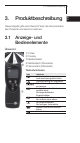
Tastenfunktionen Taste Funktionen Gerät einschalten; Gerät ausschalten (gedrückt halten) Displaybeleuchtung ein-/ausschalten Messwert halten, Maximal-/Minimalwert anzeigen Konfigurationsmodus öffnen/verlassen (gedrückt halten); Im Konfigurationsmodus: Eingabe bestätigen Im Konfigurationsmodus: Wert erhöhen, Option wählen Im Konfigurationsmodus: Wert verringern, Option wählen punktuelle und zeitliche Mittelwertbildung Volumenstrom en fr nl Fühler Display Bedientasten Batteriefach (Rückseite) Se
3. Produktbeschreibung Wichtige Displayanzeigen Anzeige Bedeutung Batteriekapazität (rechts unten im Display): · Im Batteriesymbol leuchten 4 Segmente: Batterie des Geräts ist voll · Im Batteriesymbol leuchten keine Segmente: Batterie des Geräts ist fast leer 3.2 Spannungsversorgung Die Spannungsversorgung erfolgt über eine 9V Blockbatterie (im Lieferumfang) bzw. -akku. Ein Netzbetrieb und das Laden eines Akkus im Gerät sind nicht möglich.
en fr es it Batteriefachdeckel in Pfeilrichtung schieben und abnehmen. 2 Batterie / Akku (9V-Block) einlegen. Polung beachten! 3 Batteriefach schließen: Batteriefachdeckel aufsetzen und gegen die Pfeilrichtung schieben. pt 1 Batteriefach auf der Rückseite des Gerätes öffnen: sv ² Batterie / Akku einlegen: nl Dieses Kapitel beschreibt die Handlungsschritte, die zur Inbetriebnahme des Produkts erforderlich sind. ?? Inbetriebnahme ?? 4. de 4.
5. Bedienung 5. Bedienung Dieses Kapitel beschreibt die Handlungsschritte, die beim Einsatz des Produkts häufig ausgeführt werden müssen. 5.1 Fühler anschließen Die benötigten Fühler sind fest angeschlossen bzw. integriert. Ein Anschluss von weiteren Fühlern ist nicht möglich. 5.2 Gerät ein-/ausschalten ² Gerät einschalten: i drücken. - Die Messansicht wird geöffnet: Der aktuelle Messwert wird angzeigt bzw. ----- leuchtet, wenn kein Messwert verfügbar ist.
2 Trichter-FFaktor F.FACT einstellen: Bei Messungen an Lüftungseinrichtungen mit einem Trichter muss der Parameter F.FACT aktiviert werden. Das Trichterset (Art.-Nr. 0563 4170) besteht aus einem Trichter zur Messung an Tellerventilen (200 x 200mm) und einem Trichter zur Messung an Lüftern (330 x 330mm). Der Konfigurationsmodus ist geöffnet, F.FACT leuchtet. i Mit / den Faktor aktivieren (on) oder deaktivieren (oFF) und mit bestätigen. 3 Fläche einstellen (nur bei F.
5. Bedienung 4 Gitter-FFaktor K.FACT einstellen (nur bei F.Fact oFF): Sind Teile der Querschnitssfläche verdeckt (z. B. durch Gitterstäbe), so kann dies mit Hilfe des GitterFaktors korrigiert werden. Der Gitterfaktor gibt den Anteil der freien Fläche an der Querschnittsfläche an. Beispiel: Sind 20% der Fläche verdeckt muss der Gitterfaktor 0.8 eingestellt werden (80% freie Fläche). Der Konfigurationsmodus ist geöffnet, K.FACT leuchtet. / bestätigen.
Anzeige wechseln: ² Messkanal-A i Zwischen der Anzeige von Temperatur (°C) und berechnetem Volumenstrom (m3/h) wechseln: drücken. ² Messwert halten, Maximal- / Minimalwert anzeigen: Der aktuelle Messwert kann festgehalten werden. Die Maximal- und Minimalwerte (seit dem letzten Einschalten des Geräts) können angezeigt werden. i mehrmals drücken, bis der gewünschte Wert angezeigt wird.
6. Messen 12 ² Punktuelle Mittelwertbildung durchführen: Hold, Max oder Min sind nicht aktiviert. 1 drücken. Mean leuchtet. - Die Anzahl der aufgenommenen Messwerte wird in der oberen Zeile angezeigt, der aktuelle Messwert wird in der unteren Zeile angezeigt. Option: i Zwischen der Anzeige von Temperatur (°C), Strömung (m/s) und berechnetem Volumenstrom drücken. (m3/h) wechseln: 2 Messwerte (in gewünschter Anzahl) aufnehmen: (mehrmals) drücken. 3 Messung beenden und Mittelwert berechnen: drücken.
± Gehäuse reinigen: i Das Gehäuse bei Verschmutzung mit einem feuchten Tuch (Seifenlauge) reinigen. Keine scharfen Reinigungs- oder Lösungsmittel verwenden! en fr es Dieses Kapitel beschreibt die Handlungsschritte, die zur Erhaltung der Funktionsfähigkeit und zur Verlängerung der Lebensdauer des Produkts beitragen. it Wartung und Pflege pt 7. de 7. Wartung und Pflege 13 nl Batteriefachdeckel in Pfeilrichtung schieben und abnehmen.
8. Fragen und Antworten 8. Fragen und Antworten Dieses Kapitel gibt Antworten auf häufig gestellte Fragen. Frage Mögliche Ursachen leuchtet (rechts unten · Batterie des Geräts ist im Display). fast leer. Gerät schaltet sich · Funktion Auto Off selbständig aus. ist eingeschaltet. · Restkapazität der Batterie ist zu gering. · Fühlerbruch. Anzeige: ----Displayanzeige reagiert träge Anzeige: uuuuu Anzeige: ooooo · Umgebungstemperatur ist sehr niedrig. · Zulässiger Messbereich wurde unterschritten.
9. Technische Daten 15 Genauigkeit (±1 Digit) Fühler es ?? Messrate Betriebstemperatur Lagertemperatur Stromversorgung Standzeit EG-Richtlinie Garantie it Auflösung pt Strömung (m/s), Temperatur (°C/°F) Volumenstrom (m3/h) +0.3...+20m/s 0...+50°C/+32...+122°F 0.01m/s 0.1°C / 0.1°F ±0.1m/s+1.5% v. Mw. ±0.5°C/±0.9°F Flügelradsonde 100mm, NTC-Temperatursensor (integriert) 2/s 0...+50°C / +32...+122°F -40...+85°C / -40...+185°F 1x 9V Blockbatterie/-akku ca.
Notizen
testo 417 Vane anemometer Bedienungsanleitung Instruction manual Mode d’emploi de en fr Contents 1. 2. 3. General notes ....................................................18 Safety advice......................................................19 Intended purpose ..............................................20 Product description ............................................21 3.1 3.2 4. 5. Commissioning ..................................................23 Operation .....................................
General notes General notes This chapter provides important advice on using this documentation. The documentation contains information that must be applied if the product is to be used safely and efficiently. Please read this documentation through carefully and familiarise yourself with the operation of the product before putting it to use. Keep this document to hand so that you can refer to it when necessary. Identification Representation Meaning ±, 1, 2 Note Objective Condition i, 1, 2, ...
Avoid personal injury/damage to equipment i Do not use the measuring instrument and probes to measure on or near live parts. en fr This chapter gives general rules which must be followed and observed if the product is to be handled safely. es Safety advice it 1. de 1. Safety advice 19 Product safety/preserving warranty claims sv with solvents and do not use any desiccants.
2. Intended purpose 2. Intended purpose This chapter gives the areas of application for which the product is intended. Use the product only for those applications for which it was designed. Ask Testo if you are in any doubt. testo 417 is a compact measuring instrument for measuring flow velocities and temperatures by means of an integrated 100mm vane with temperature probe.
Button functions Button Functions Switch instrument on; switch instrument off (press and hold) Switch display light on / off Keep reading, display maximum/minimum value Open/leave configuration mode (press and hold); In configuration mode: Confirm input In configuration mode: Increase value, select option In configuration mode: Reduce value, select option Multi-point and timed mean calculation Volumetric flow en fr nl Probe Display Control buttons Battery compartment (rear) Service compartment
3. Production description Important displays Display Meaning Battery capacity (bottom right in display): · 4 segments in the battery symbol are lit: Instrument battery is fully charged · No segments in the battery symbol are lit: Battery is almost spent 3.2 Voltage supply Voltage is supplied by means of a 9V monobloc battery (included in delivery) or rechargeable battery. It is not possible to run the instrument from the mains supply or charge a rechargeable battery in the instrument.
en fr es it instrument, push the lid of the battery compartment in the direction of the arrow and remove it. 2 Insert a battery/rechargeable battery (9V monobloc). Observe the polarity! 3 To close the battery compartment, replace the lid of the battery compartment in position and push it against the direction of the arrow. pt 1 To open the battery compartment on the rear of the sv ² Inserting a battery/rechargeable battery: nl This chapter describes the steps required to commission the product.
5. Operation 5. Operation This chapter describes the steps that have to be executed frequently when using the product. 5.1 Connecting a probe The necessary probes are permanently connected or integrated. It is not possible to connect any additional probes. 5.2 Switching the instrument on / off ² Switching the instrument on: i Press . - Measurement view is opened: The current reading is displayed, or ----- lights up if no reading is available.
5. Operation 25 de 5.4 Performing settings For measurements at ventilation outlets with a funnel the parameter F.FACT must be activated. The funnel set (order no. 0563 4170) consists of a funnel for measurements at plate outlets (200 x 200mm) and a funnel for measurements at ventilation outlets (330 x 330mm). Configuration mode is opened, F.FACT is lit. i Activate (on) or deactivate (oFF) the factor with and confirm with . 3 To set the area (only if F.
5. Operation 4 To set the grill factor: K.FACT (only if F.Fact oFF): If parts of the cross-sectional area are covered (e.g. by grill members), this can be corrected via the grill factor. The grill factor indicates the proportion of free space on the cross-sectional area. Example: If 20% of the area is covered, the grill factor must be set to 0.8 (80% free space) Configuration mode is opened, K.FACT is lit. i Set the grill factor with / and confirm with .
view. i Put the probe in position and read off the readings. ² Changing the measurement channel display: i To change between displaying the temperature (°C) and the calculated volumetric flow rate (m3/h): Press . en fr es The instrument is switched on and is in measurement it ² Taking a measurement: pt This chapter describes the steps that are required to perform measurements with the product. sv Measuring nl 6. de 6. Measuring 27 value: ?? The current reading can be recorded.
6. Measuring point mean calculation: ² Performing a multi-p Hold, Max or Min are not activated. 1 Press . Mean is lit. - The number of readings recorded is displayed in the upper line, while the current reading is displayed in the lower line. Option: i To change between displaying the temperature (°C), flow velocity (m/s) and calculated volumetric flow . rate (m3/h): Press 2 To include readings (in the desired quantity): Press (several times).
± Changing the battery/rechargeable battery: The instrument is switched off. 1 To open the battery compartment on the rear of the instrument, push the lid of the battery compartment in the direction of the arrow and remove it. 2 Remove the spent battery/rechargeable battery and insert a new battery/rechargeable battery (9 V monobloc). Observe the polarity! 3 To close the battery compartment, replace the lid of the battery compartment in position and push it against the direction of the arrow.
8. Questions and answers 8. Questions and answers This chapter gives answers to frequently asked questions. Question Possible causes Possible solution is lit (bottom right in display). Instrument switches itself off automatically. · Instrument battery is almost spent. · Auto Off function is switched on. · Residual capacity of battery is too low. · Probe break. · Replace instrument battery. · Switch function off.
9. Technical data 31 Characteristic de Technical data en 9. Value Flow velocity (m/s), temperature (°C/°F) Volumetric flow rate (m3/h) +0.3...+20m/s 0...+50°C/+32...+122°F Resolution 0.01m/s 0.1°C / 0.1°F Accuracy ±0.1m/s+1.5% of reading (± 1 Digit) ±0.5°C/±0.9°F Probe Vane probe 100mm, NTC temperature probe (integrated) Measuring rate 2/s Operating temperature range 0...+50°C / +32...+122°F Storage temperature -40...+85°C / -40...+185°F Voltage supply 1x 9V monobloc battery/rech.
Notes
testo 417 Anémomètre à hélice Bedienungsanleitung Instruction manual Mode d’emploi de en fr Sommaire 1. 2. 3. Recommandations générales ............................34 Consigne de sécurité..........................................35 Utilisation conforme à l’application......................36 Description du produit ........................................37 3.1 3.2 4. 5. Mise en service ..................................................39 Fonctionnement ................................................
Recommandations générales Recommandations générales Ce chapitre donne des recommandations générales pour l'utilisation de ce document. Ce document comporte des informations devant être prises en compte pour une utilisation efficace du produit en toute sécurité. Veuillez, attentivement, prendre connaissance de ce document et familiarisez-vous avec le maniement du produit avant de l'utiliser. Conservez-le à portée de main afin de pouvoir y recourir en cas de besoin.
ou avec les capteurs sur ou à proximité d'éléments conducteurs. i Ne stockez jamais l'appareil/les cellules de mesure conjointement avec des solvants, n'utilisez pas de dessicateur. Assurer la sécurité du produit/Conserver le droit à la garantie en fr es i Ne réalisez pas de mesures avec l'appareil de mesure it Eviter les dommages matériels/corporels pt Ce chapitre fournit des règles générales devant absolument être respectées pour utiliser l'appareil en toute sécurité.
2. Utilisation conforme à l’application 2. Utilisation conforme à l’application Ce chapitre comporte les domaines d'utilisation pour lesquels le produit est destiné. N'utilisez le produit que dans les domaines pour lesquels il est conçu. En cas de doute, vérifiez auprès de testo. Le testo 417 est un appareil de mesure compact pour la mesure de vitesse d'air et de température à l'aide d'une hélice intégrée de 100mm associée à une sonde de température.
Fonctions des touches Touche Fonctions Allumer l’appareil; Eteindre l’appareil (maintenir appuyé) Allumer/éteindre l’éclairage de l’affichage Conserver une donnée de mesure, afficher valeurs max/min Ouvrir/quitter module de configuration (Maintenir appuyé).
3. Description du produit Eléments importants de l’affichage Affichage Signification Capacité de batterie (partie inférieure droite de l'affichage) : · 4 segments sont affichés dans le symbole de la pile : la pile est en pleine charge · Aucun segment n'apparaît dans le symbole de la pile : la pile de l'appareil est quasiment vide 3.2 Alimentation L’alimentation est réalisée avec une pile de 9V ou accu (en option).
en fr es it Faites glisser le couvercle du compartiment pile dans le sens de la flèche puis retirez-le. 2 Insérer la pile / accu (9V monobloc). Respectez la polarité! 3 Fermez le compartiment pile : Repositionnez le couvercle du compartiment pile et faites glisser dans le sens opposé de la flèche. pt 1 Ouvrez le compartiment pile au dos de l'appareil : sv ² Insérer la pile / l’accu : nl Ce chapitre décrit les étapes nécessaires à la mise en service du produit. ?? Mise en service ?? 4. de 4.
5. Fonctionnement 5. Fonctionnement Ce chapitre décrit les manipulations devant souvent être effectuées lors de l'utilisation du produit. 5.1 Raccorder la sonde Les sondes nécessaires sont fixes ou intégrées. Il n'est pas possible de raccorder d'autres sondes. 5.2 Allumer/éteindre l’appareil ² Allumer l’appareil : i Appuyez sur .- La valeur de mesure actuelle est affichée ou ------ apparaît, si aucune valeur de mesure n'est disponible.. ² Eteindre l’appareil : i Maintenez appuyé (env.
5. Fonctionnement 41 de 5.4 Paramétrage 2 To set funnel factor F.FACT: Pour des mesures en sorties de bouche avec un cône de mesure, le paramètre F.FACT doit être activé. Le set cône (Réf. 0563 4170) est composé d’un cône pour VMC (200x200mm) et d’un cône pour ventilation (330x330mm) Le mode configuration est activé, F.FACT est allumé. i Activer (on) ou désactiver (oFF) le facteur avec et confirmer avec / . 3 Paramétrer la surface (uniquement si F.
5. Fonctionnement 4 Paramétrer le facteur de grille: K.FACT (uniquement si F.FACT oFF): Lorsque la section est partiellement recouverte (par exemple par une grille), ceci peut être corrigé à l'aide du facteur de grille. Le facteur de grille indique la part de la surface libre sur la section. Par exemple : lorsque 20% de la section sont recouverts, il faudra paramétrer le facteur de grille 0,8 (80%de surface libre). Le mode configuration s'ouvre, K.
L'appareil est allumé et se trouve en mode aperçu. i Positionnez la sonde et lisez les valeurs mesurées. ² Changer d’affichage de canal de mesure: i Passez de l'affichage de la température (°C) au débit calculé : appuyez sur . en fr es ² Réaliser des mesures : it Ce chapitre décrit les étapes nécessaires à réaliser des mesures avec ce produit. pt Mesures sv 6. de 6. Mesures 43 i Appuyez plusieurs fois sur jusqu'à ce que la valeur souhaitée soit affichée.
6. Mesures ² Mesurer une moyenne ponctuelle : Hold, Max, Min ne sont pas activés. 1 Appuyez sur . Mean apparaît. - Le nombre de valeurs relevées est affiché dans la ligne supérieure, la valeur de mesure actuelle est affichée dans la ligne inférieure. Option: i Passer de l'affichage de la température (°C),à la vitesse d’air (m/s) puis au débit (m3/h) : Appuyez sur . 2 Relever des valeurs de mesure (quantité au choix) : appuyez sur (plusieurs fois).
en Maintenance et entretien i En cas de salissure, nettoyez le boîtier avec un linge humide (eau savonneuse). N'utilisez pas de solvants ni de produits de nettoyage forts ! it pt ± Nettoyage du boîtier : sv Ce chapitre décrit les étapes contribuant au maintien des fonctionnalités et à la prolongation de la durée de vie du produit. es fr 7. de 7. Maintenance et entretien 45 Faites glisser le couvercle du compartiment pile dans le sens de la flèche puis retirez-le.
8. Questions / Réponses 8. Questions / Réponses Ce chapitre donne des réponses à des questions fréquemment posées. Question Causes possibles apparaît (dans la partie · La pile de l'appareil est inférieure gauche de l'affichage) presque vide. L’appareil s’éteint auto· La fonction AUTO OFF matiquement. est activée · La capacité résiduelle de la pile est trop faible.
9. Caractéristiques techniques 47 en de Caractéristiques techniques it Valeurs Vitesse d’air (m/s), température (°C/°F) Débit (m3/h) +0,3…+20 m/s0…+50°C/+32…+122°F 0,01 m/s0,1°C/0,1°F ± 0,1 m/s +1,5% val. moy.± 0,5°C/± 0,9°F Sonde à hélice 100 mm , Capteur de température CTN ?? ?? nl 2/s 0…+50°C/+32…+122°F -40…+85°C/-40…+185°F 1x9v bloc pile/accu env. 50h IP 65 2004/108/CEE 2 ans 10.
Postfach 11 40, 79849 Lenzkirch Testo-Straße 1, 79853 Lenzkirch Telefon: (0 76 53) 6 81 - 0 Fax: (0 76 53) 6 81 - 1 00 E-Mail: info@testo.de Internet: http://www.testo.com www.testo.com testo AG 0977.