testo 310 · Flue gas analyzer Instruction manual [en-US]
1 Contents 1 Contents 1 Contents ...................................................................................................3 2 Safety and the environment ....................................................................5 2.1. About this document ........................................................................5 2.2. Ensure safety...................................................................................6 2.3. Protecting the environment .......................................
1 Contents 6.2. 6.3. 6.4. 7 4 Cleaning the flue gas probe .......................................................... 26 Draining the condensate container ............................................... 26 Checking / replacing the particle filter ........................................... 27 Tips and assistance .............................................................................. 28 7.1. Questions and answers ................................................................ 28 7.2.
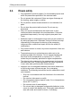
2 Safety and the environment 2 Safety and the environment 2.1. About this document Note > Please read this documentation through carefully and familiarize yourself with the product before putting it to use. Pay particular attention to the safety instructions and warning advice in order to prevent injuries and damage to the products. > Keep this document so you can refer to it when necessary. > Hand this documentation on to any additional or subsequent users of the product.
2 Safety and the environment 2.2. Ensure safety > Only operate the product properly, for its intended purpose and within the parameters specified in the technical data. > Do not operate the instrument if there are signs of damage at the housing, power supply or cables. > Do not perform contact measurements on non-insulated, live parts. > Do not store the product with solvents. Do not use any desiccants.
3 Technical Specifications • • • 2.3. Only charge in the instrument or the recommended charging station. Immediately stop the charging process if this is not completed in the given time. In the event of improper function or signs of overheating, immediately remove the rechargeable battery from the measuring instrument/charging station.
3 Technical Specifications 3.2. 3.2.1. Technical data Measurement ranges and resolution Measurement parameter Measurement range Resolution Accuracy Response time t90 O2 0.0 to 21.0 Vol.% 0.1 vol.% ±0.2 vol.% 30s CO 0 to 4000 ppm 1 ppm ±20 ppm (0 to 400 ppm) ±5% of meas. val. (401 to 2000 ppm) ±10% of meas. val. (2001 to 4000 ppm) 60s COamb 0 to 4000 ppm 1 ppm ±20 ppm (0 to 400 ppm) ±5% of meas. val. (401 to 2000 ppm) ±10% of meas. val. (2001 to 4000 ppm) 60s Draft -8.03 to 8.
3 Technical Specifications 3.2.2. Other instrument data Flue gas analyser Feature Values Storage and transport temperature -4 to 122°F (-20 to 50 °C) Operating temperature 23 to 113°F (-5 to 45 °C) Power supply Rechargeable battery: 1500mAh Mains unit: 5 V/1 A Protection class IP40 Weight incl. probe approx. 1,54lbs (approx. 700g) Dimensions 7.9 x 3.3 x 1.7 inch (201 x 83 x 44 mm) Battery charge time Approx.
4 Product description 4 Product description 4.1. Measuring instrument 4.1.1. Front view 1 2 3 4.1.2.
4 Product description 4.1.3. Button Functions [esc] Back, cancel print process [ ] Switch display light on/off [ ] Transmit data to the Testo protocol printer.
4 Product description 2 Status: Icon Meaning Measuring gas pump (icon visible when the instrument is switched off) The inner segments light up alternately when the measuring gas pump is running. Error Flashes when an error occurs, an error code is also displayed. Print Lights up during data transmission to the report printer change to next measurement type Fuel type / instrument fuel number Depending on the set fuel, one of the icons (solid fuel, oil, gas) and the associated fuel number lights up.
4 Product description 5 Measurement function key assignment: Icon Possible assignment Left function key: Start print process Select measurement type 4.1.4. Middle function key: Confirm input Start measurement Stop measurement Set Right function key: Open configuration menu Switch to the next parameter: Connections 1 2 3 4.1.5.
4 Product description 4.1.6. Rear view 1 2 3 4 5 Attachment for carrying strap Condensate trap Magnetic holder Gas outlet Magnetic holder CAUTION Damage to other equipment caused by strong magnets! > Keep a safe distance from products which could be damaged by magnets (e.g. monitors, computers, pacemakers, credit cards).
4 Product description 4.2. Flue gas probe 1 2 3 4 5 4.3. Thermocouple Probe shaft Probe handle Connecting cable Removable filter chamber with window, particle filter, and sealing plug for differential pressure measurement Country versions The instrument can be configured for four area versions. Countryspecific calculation formulas, associated measurement parameters and fuels are activated with this setting. Similarly, the setting influences the date and time format.
4 Product description Country Countries Parameters Fuels version (recommend (ArEA ) ation) 16 1 USA, HU, IN, Line 1: KR O2, T, CO , P1, P2, uCO Line 2: CO, Eff, T, EXA, CO2 nAt GAS – Natural gas ProP GAS – Propane FUEL OIL2 – Fuel oil 2 Bioh 5 – Biomass 5% Uood 20 – Wood 20% 2 GB, RU, IT, CZ, DK, AU, JP, CN Line 1: rat, O2, T, P1, CO , P2, uCO Line 2: CO2, CO, EXA, Eff.net, Eff.
4 Product description 4.4. Reading display Display T Measurement parameter Ambient temperature T Flue gas temperature CO Carbon monoxide O2 Oxygen CO Ambient carbon monoxide qA Flue gas loss without the latent heat of condensation Eff.net Net efficiency (without the latent heat of condensation) Eff.
5 Using the product 5 Using the product 5.1. Power Supply/ rechargeable battery The rechargeable battery is permanently installed and can only be changed by a Testo service center. The measuring instrument is supplied with a partially charged rechargeable battery. > Charge the rechargeable battery fully before using the measuring instrument. 5.1.1. Charging the rechargeable battery The rechargeable battery can only be charged at an ambient temperature of ±0 to +35°C (±32 to + 95°F).
5 Using the product - 5.2. If the measuring instrument is switched off, the charging process starts automatically. Switching the measuring instrument on has the effect of stopping the battery charging and the measuring instrument is then powered via the AC power unit. Performing settings The instrument has two different configuration menus. The menu that is opened depends on the instrument status. 5.2.1.
5 Using the product 5.2.2. Display / parameter Explanation Setting the time > Set values: [▲] and [▼]. > Switch selection between hour, minute (tens) and minute (single units): []. > Switch to the next parameter: [OK]. Setting the date > Set values: [▲] and [▼]. > Switch selection between year (tens), year (single units), month, day (tens) and day (single units): []. > Exit the configuration menu: [OK].
5 Using the product 5.3. Measuring 5.3.1. Preparing for measurement 5.3.1.1. Zeroing phases Gas sensors If flue gas measurement ( ) or ambient CO measurement ( ) is configured, the gas sensors are zeroed when the instrument is switched on (zeroing phase). The flue gas probe must be in clean ambient air during the zeroing phase! Pressure sensor If draft measurement ( ) or pressure measurement ( ) is configured, the pressure sensor is zeroed when the instrument is switched on (zeroing phase).
5 Using the product Aligning the flue gas probe The flue gas must be able to flow freely past the thermocouple. > Align the probe by turning it as required. The tip of the probe must be in the core current of the flue gas flow. > Align the flue gas probe in the flue gas duct so that the tip is in the core current (area of the highest flue gas temperature). 5.3.1.3. Setting fuel To carry out a flue gas measurement, the fuel must be set correctly, see Measurements configuration menu, page 20. 5.3.2.
5 Using the product 5.3.3. Ambient CO Cigarette smoke influences the measurement by more than 50 ppm. The breath of a smoker influences the measurement by about 5 ppm. The probe must be in the open air (CO-free) during the zeroing phase! Select measurement type > Select :[ ] → [OK]. Perform the measurement 1. Start measurement: [Start]. - The reading is displayed. 2. Quit measurement: [Stop]. 3. 5.3.4.
5 Using the product 5.3.5. Pressure WARNING Dangerous mixture of gases Danger of explosions. > Before measurement close the gas path with the sealing plug, as described below! > Make sure there are no leaks between the sampling point and the measuring instrument. > Do not smoke or use naked flames during measurement. Do not measure for longer than 5 min, as a drift of the pressure sensor means that the readings could be outside the tolerance limits. Select measurement type > Select :[ ] → [OK].
5 Using the product 4. Close the gas path with the sealing plug. 5. Check that the sealing plug is fitted tightly. It should not yield at all on being tugged gently. CAUTION Hot probe shaft! Risk of burns! > Allow the probe shaft to cool down after a measurement, before touching it! > Only attach the silicone hose to the probe shaft once it has cooled down! 6. Fit silicone hose onto the probe shaft of the flue gas probe. The probe shaft openings must be closed.
6 Maintaining the product 6 6.1. Maintaining the product Cleaning the measuring instrument > If the housing of the measuring instrument is dirty, clean it with a damp cloth. Do not use any aggressive cleaning agents or solvents! Mild household cleaning agents and soap suds may be used. 6.2. Cleaning the flue gas probe > In case of contamination, clean the probe shaft and the handle of the flue gas probe with a damp cloth.
6 Maintaining the product 2. Open the sealing plug of the condensate trap. 3. Let the condensate drain. 4. Dab off any remaining drops on the condensate outlet with a cloth. 5. Close condensate outlet with sealing plug and press firmly. The condensate outlet must be completely closed, otherwise measuring errors could occur if external air leaks in. 6.4.
7 Tips and assistance 7 Tips and assistance 7.1. Questions and answers 28 Question Possible causes / solution Rechargeable battery low > Connect to AC power supply. Measuring instrument switches off automatically or cannot be switch on Batteries / rechargeable batteries empty. > Charge rechargeable battery or switch to AC power supply. When switching off, the instrument rinses the gas path for a long time and does not shut down. The gas path is closed by the sealing plug.
7 Tips and assistance Question Possible causes / solution Error message: E14 Checksum error > Critical error, contact Testo Service Error message: E15 Instrument temperature is outside the permissible range > Adjust instrument to the permissible ambient temperature (see Technical data) Is it possible to print out company data? Company data should be displayed in the header of the print-out. > Input of your personal data can be done by Testo service.
Testo Inc. 40 White Lake Road Sparta, N. J. 07871 Phone: +1 862 354 5001 Fax: +1 862 354 5020 Email: info@testo.com www.testo.us 0970 3100 en-US 01 V01.