testo 550s / testo 557s digital manifold Instruction manual
Contents Contents 1 2 3 4 5 6 6.1 About this document ...........................................................................5 Safety and disposal..............................................................................5 Product-specific approvals .................................................................5 Product-specific information...............................................................6 Use.........................................................................................
Contents 8.4 Settings ............................................................................................................ 36 8.4.1 Backlight duration .................................................................................................... 37 8.4.2 Backlight brightness................................................................................................. 38 8.4.3 Auto Off ....................................................................................................
Contents 9.9 testo DataControl archiving software ................................................................ 66 9.9.1 System requirements ...............................................................................................66 9.9.1.1 Operating system ....................................................................................................................66 9.9.1.2 PC.............................................................................................................
1 About this document 1 About this document • The instruction manual is an integral part of the instrument. • Pay particular attention to the safety instructions and warning advice in order to prevent injury and damage to the product. • Please read this instruction manual through carefully and familiarize yourself with the product before putting it to use. • Familiarity with a PC as well as the Microsoft® products is assumed in this documentation.
4 Product-specific information 4 Product-specific information • The measuring instrument being dropped or any other comparable mechanical stress may cause breakage of the pipe pieces in the refrigerant hoses. The valve positioners may also suffer damage, causing further damage inside the measuring instrument that is not necessarily visible externally. Therefore, always replace the refrigerant hoses with new ones after the measuring instrument is dropped or after any comparable mechanical stress.
5 Use 5 Use testo 550s and testo 557s are digital manifolds for maintenance and service work on refrigeration systems and heat pumps. They may only be used by qualified authorized personnel. The functions of the instruments testo 550s and testo 557s mean they can replace mechanical manifolds, thermometers and pressure/temperature charts. Pressures and temperatures can be applied, adapted, tested and monitored.
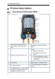
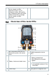
6 Product description 6 Product description 6.1 Overview of the testo 550s Mini-DIN probe socket for NTC 1 temperature probe, with socket cover 2 Foldable suspension device (rear). Rear • Battery compartment • 3 Display.
6 Product description release screw fitting; passage can be closed via valve positioner Centre: e.g. for refrigerant bottles, with sealing cap, refrigerant hoses with quickrelease screw fitting; passage can be closed via valve positioner. 6.2 Overview of the testo 557s Mini-DIN probe socket for NTC 1 temperature probe, with socket cover 2 Foldable suspension device (rear). Rear • Battery compartment • Mini USB port for firmware update 3 Display.
6 Product description 7 4 x valve positioner Connection 7/16" UNF, brass. High pressure, for refrigerant 9 hoses with quick-release screw fitting, passage can be closed via valve positioner. Connection 7/16" UNF, brass, 11 e.g. for refrigerant cylinders, with sealing cap 6.3 4 x hose bracket for refrigerant hoses 10 Connection 5/8" UNF, brass, for vacuum pump Connection 7/16" UNF, brass.
7 First steps Control keys 6.4 Symbol Meaning • Open menu • Confirm input • Switch on the display illumination: Press and hold the key for >2s • Switch off the display illumination: Press and hold the key for >2s Change/navigate the display screen. / • Switches to the measurement view • Back to the menu • Switch off the instrument: Press and hold the key for >2s 7 First steps Inserting (rechargeable) batteries 7.
7 First steps Switching the instrument on and off 7.2 Current status Action Instrument off Press Function Instrument is switched on. When the measuring instrument is started for the first time, the setup wizard guides you through the following setting parameters step by step: - Language - testo Smart App Instrument on Press and hold down (> 2 s) Instrument is switched off. The instrument setup that is implemented can be adapted at any time in the Settings menu. 7.
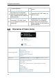
8 Using the product 2 Take a photo of the QR code of the testo Smart App and press [Menu/Enter] to confirm. - The measurement menu is displayed. 8 Using the product Preparing for measurement 8.1 8.1.1 Operating the valve positioners With respect to the refrigerant path, the digital manifold behaves just like a conventional four-way manifold (only applies to the testo 557s): The passages are opened by opening the valves. The applied pressure is measured with the valves closed and the valves opened.
8 Using the product 8.1.2 Automatic mode The manifold automatically detects the pressure difference between the lowpressure and high-pressure sides. If the measured pressure on the low pressure side is 1 bar higher than on the high pressure side, a dialogue appears and the display can be changed accordingly. If “yes” is selected, the low pressure moves from left to right and the high pressure moves from right to left.
8 Using the product • Superheating • Subcooling An NTC temperature probe (accessory) must be connected for measuring the pipe temperature and for automatic calculation of superheating and subcooling. These can be fixed cable temperature probes or Testo Smart Probes (e.g. testo 115i). Before each measurement, check that the refrigerant hoses are in flawless condition. Before each measurement, zero the pressure sensors. All connections must be pressureless (ambient pressure).
8 Using the product 3 Select Refrigeration and press [Menu/Enter] to confirm. - The measurement menu is displayed. 4 Connect the refrigerant hoses. 4.1 Close the valve positioners. 4.2 Connect the refrigerant hoses for low-pressure side (blue) and highpressure side (red) to the measuring instrument. 4.3 Connect the refrigerant hoses to the system. 5 Connect testo 115i or fixed cable probes.
8 Using the product 6 Set refrigerant. 6.1 Press the key [▼] (Rxx) (refrigerant number according to ISO 817). - The refrigerant menu opens and the current refrigerant is highlighted. 6.2 Setting the refrigerant: Press [▲] or [▼] to select the refrigerant and press [Menu/Enter] to confirm. You have the option of setting up favourite refrigerants on your instrument and in the app. These then appear at the beginning of the refrigerant list.
8 Using the product 8 Pressurize the measuring instrument. - The measurement starts automatically. - Measurement results are displayed: • Low/high pressure • Condensation and evaporation temperature • Suction and liquid line temperature • Superheating and subcooling With zeotropic refrigerants, the evaporation temperature to/Ev is displayed after complete evaporation/the condensation temperature tc/Co is displayed after complete condensation.
8 Using the product 8.2.2 Evacuation Via the Evacuation application, foreign gases and moisture can be removed from the refrigeration circuit. The testo 552i is recommended for carrying out the measurement. The measurement is also possible without the testo 552i, with testo 550s/testo 557s. However, this is not advisable due to insufficient accuracy. The instrument is switched on and the measurement menu is displayed. ® Bluetooth is enabled. Hoses are connected. 1 Press [Menu/Enter].
8 Using the product 3 Press [▲] / [▼] to select Evacuation and press [Menu/Enter] to confirm. - The Configure Target Lines menu is displayed. 4 Adjust the Target Line value 4.1 Press the [▲] key and in the Evacuation Target field, select Manual Input. 4.2 Press [Menu/Enter] to confirm. - The field is activated. 4.3 Press [▲] / [▼] to set the value. 4.4 Press [Menu/Enter] to confirm. 5 Adjust the Maximum Decay Target value. 5.1 Press the [▼] key and in the Maximum Decay Target field, select Manual Input.
8 Using the product 5.2 Press [Menu/Enter] to confirm. - The field is activated. 5.3 Press [▲] / [▼] to set the value. 5.4 Press [Menu/Enter] to confirm. 6 Confirm the entries in steps 4 and 5: Press [▼] to select OK and press [Menu/Enter] to confirm. - A connection is established with available Bluetooth® probes. - testo 552i is switched on and connected automatically. - The Evacuation measurement menu is displayed.
8 Using the product 7 Start measurement: Press the [▼] (Start) key. - Once the measuring range 0 to 20,000 microns / 0 to 26.66 mbar is reached, the current vacuum value is shown on the instrument display. The instrument also displays the current ambient temperature, the water evaporation temperature which corresponds to the vacuum reading, and the delta between these two temperatures. 8 End measurement: Press the [▼] (Stop) key. - The measurement result is displayed.
8 Using the product The testo 550s or testo 557s manifold is used to carry out the measurement. The instrument is switched on and the measurement menu is displayed. Hoses are connected. 1 Press [Menu/Enter]. 2 Press [▲] / [▼] to select Measuring Mode and press [Menu/Enter] to confirm. - The Measuring Mode menu is displayed. 3 Press [▲] / [▼] to select Pressure Leak Test and press [Menu/Enter] to confirm.
8 Using the product - For the temperature-compensated leak test, a connection is established with available Bluetooth® probes. If cable probes are connected to the instrument, they are prioritized for the compensation. Please note that only air probes are ideal for temperaturecompensated leakage testing. - testo 905i / testo 605i is switched on and automatically connected. Other temperature probes compatible with testo 550s / testo 557s can be connected. - The Pressure Leak Test menu is displayed.
8 Using the product Target Superheat 8.2.4 This feature makes it possible to connect the testo 550s and testo 557s manifolds to two additional testo 605i Smart Probes in order to calculate the target superheat. This application can only be used for split air conditioning systems/heat pumps with a fixed expansion valve. The two connected testo 605i Smart Probes determine the ODDB and RAWB values. The target superheat value appears on the display as a result.
8 Using the product - The Measuring Mode menu is displayed. 3 Press [▲] / [▼] to select Target Superheat and press [Menu/Enter] to confirm. - The Configure Target Superheat menu is displayed. The values can either be configured manually via Manual Input or recorded by the testo 605i via Smart Probe. When a Smart Probe is selected, available testo 650i instruments are displayed for the connection. 4 Adjust values for Outdoor Dry Bulb Temp. 4.1 Press the [▲] key and in the Outdoor Dry Bulb Temp.
8 Using the product 5.1 Press the [▲] / [▼] key and in the Return Air Wet Bulb Temp. field, select Manual Input. 5.2 Press [Menu/Enter] to confirm. - The field is activated. 5.3 Press [▲] / [▼] to set the value. 5.4 Press [Menu/Enter] to confirm. 6 Confirm the entries in steps 4 and 5: Press [▼] to select Okay and press [Menu/Enter] to confirm. - The Target Superheat measurement menu is displayed. 7 Connect the refrigerant hoses. 7.1 Close the valve positioners.
8 Using the product 7.2 Connect the refrigerant hoses for low-pressure side (blue) and highpressure side (red) to the measuring instrument. 7.3 Connect the refrigerant hoses to the system. 8 Connect testo 115i/fixed cable probes. 9 Set refrigerant. 9.1 Press the key [▼] (Rxx) (refrigerant number according to ISO 817). - The refrigerant menu opens and the current refrigerant is highlighted. 9.2 Setting the refrigerant: Press [▲] or [▼] to select the refrigerant and press [Menu/Enter] to confirm.
8 Using the product 8.2.5 Compressor Test (DLT) For this mode, 3 temperature probes are used. In addition to the conventional temperature sensors for superheating and subcooling, an additional temperature probe must be connected via Bluetooth. The testo 115i (clamp thermometer) or fixed cable probes are used to carry out the measurement. Before each measurement, check that the refrigerant hoses are in flawless condition. Before each measurement, zero the pressure sensors.
8 Using the product 3 Press [▲] / [▼] to select Compressor Test (DLT) and press [Menu/Enter] to confirm. The measurement menu is displayed. The DLT temperature is shown on the display. 4 Connect the refrigerant hoses. 4.1 Close the valve positioners. 4.2 Connect the refrigerant hoses for low-pressure side (blue) and highpressure side (red) to the measuring instrument. 4.3 Connect the refrigerant hoses to the system.
8 Using the product 6.2 Setting the refrigerant: Press [▲] or [▼] to select the refrigerant and press [Menu/Enter] to confirm. - The newly set refrigerant is displayed in the refrigerant list. 7 Press the [▲] (P=O) key for 2 seconds to carry out zeroing. - Zeroing takes place. 8 Pressurize the measuring instrument. - The measurement starts automatically. - The measurement result is displayed. 9 Press [Menu/Enter] to return to the main menu. 8.2.6 Delta T Temperature 1 and temperature 2 are measured.
8 Using the product 3 Press [▲] / [▼] to select Measuring Mode and press [Menu/Enter] to confirm. - The Measuring Mode menu is displayed. 4 Press [▲] / [▼] to select Delta T and press [Menu/Enter] to confirm. - The measurement result is displayed. 5 Press [Menu/Enter] to return to the main menu.
8 Using the product 8.3 Bluetooth testo 550s / testo 557s have the option of establishing a Bluetooth® connection with wireless probes as well as a connection to the testo Smart App at the same time. If the testo 550s or testo 557s is used with Smart Probes, they must be at least 20 cm apart. 8.3.1 Probes compatible with the instrument Smart Probes Order no.
8 Using the product 8.3.2 Establishing a connection To establish a connection via Bluetooth®, you need a tablet or smartphone with the Testo Smart App installed on it. You can get the App for iOS instruments in the App Store or for Android instruments in the Play Store. Compatibility: Requires iOS 12.0 or later/Android 6.0 or later, requires Bluetooth® 4.0. Once the connection between the app and the Testo manifold has been successfully established, the app is in second screen mode.
8 Using the product 8.3.3.1 Switching on The Bluetooth menu is selected. 1 [Menu/Enter] - In the On/Off switch icon, displayed. is 2 Enable Bluetooth®: Press [▼] to activate the [Completed] button and press [Menu/Enter] to confirm. - When the Bluetooth® icon is shown on the display, Bluetooth is switched on. - Bluetooth® automatically searches for and connects available probes. - After opening the App, the instrument is automatically connected if it is within range.
8 Using the product Manual probe selection 8.3.3.3 If this menu is activated, it appears before a measurement. The Bluetooth® menu is activated (in the On/Off switch icon, displayed. is 1 Press [▼] to select Manual probe selection. Enable function: Via [Menu/Enter], set the switch to [ON]. An info window with the available probes appears before each measurement to be carried out. The information must be confirmed by pressing [Menu/Enter]/[Okay].
8 Using the product 2 Select Settings: Press [▼] and then [Menu/Enter] to confirm. - The Settings menu is displayed. Available settings: • Backlight duration 8.4.1 • Backlight brightness • Auto Off • Auto Tfac (Temperature compensation factor) • Units • Language • Setup Wizard • Restore factory settings • Instrument information Backlight duration Set the backlight duration for the display. The Settings menu is activated.
8 Using the product 2 Press [▲] / [▼] to select the backlight duration and press [Menu/Enter] to confirm. 3 Press [ESC]: 1x main menu view, 2 x measurement menu view. 8.4.2 Backlight brightness Set the brightness for the display. The Settings menu is activated. 1 Press [▲] / [▼] to select Backlight brightness and press [Menu/Enter] to confirm. - Menu properties are displayed. 2 Press [▲] / [▼] to select the brightness value (25%, 50%, 75%, 100%) and press [Menu/Enter] to confirm.
8 Using the product Auto Off 8.4.3 You can manage the energy consumption for your instrument yourself. The Settings menu is activated. 1 Press [▲] / [▼] to select [Auto OFF] and press [Menu/Enter] to confirm. - Menu properties are displayed. 2 Select using [▲] / [▼] • On: The instrument automatically switches off after 30 minutes of inactivity. The instrument switches off automatically if no pressure is measured and no key was pressed within 10 minutes.
8 Using the product 8.4.4 Auto Tfac (Temperature compensation factor) A surface compensation factor has been set in the measuring instrument to reduce the measuring errors in the main field of applications. This reduces measuring errors when using surface temperature probes. Surface temperature probe An NTC temperature probe (accessory) must be connected for measuring the pipe temperature and for automatic calculation of superheating and subcooling. The Settings menu is activated.
8 Using the product 8.4.5 Units The Settings menu is activated. 1 Press [▲] / [▼] to select [Units] and press [Menu/Enter] to confirm. - Menu properties are displayed. Adjustable units Measurement parameter Unit Description Temperature °C, °F Set unit for temperature. Pressure psi, kPa, MPa, bar Set unit for pressure. Prel, Pabs Depending on the chosen unit for pressure: Change between absolute and relative pressure displays.
8 Using the product 3 Press [ESC]: 1 x Unitsmenu, 2 x main menu view, 3 x measurement menu view. 8.4.6 Language The Settings menu is activated. 1 Press [▲] / [▼] to select [Language] and press [Menu/Enter] to confirm. - Menu properties are displayed. 2 Select language: Press [▲] / [▼] and [Menu/Enter] to confirm. Selecting the language activates the appropriate presetting of the units of measurement. 3 Press [ESC]: 1 x Units menu, 2 x main menu view, 3 x measurement menu view.
8 Using the product 8.4.7 Setup Wizard The Settings menu is activated. 1 Press [▲] / [▼] to select [Setup Wizard] and press [Menu/Enter] to confirm. - Language selection opens. 2 Press [▲] / [▼] to select the language. - The units for the respective country are set automatically. - Barcode is displayed and the app can be downloaded from the respective app store.
8 Using the product 8.4.8 Restore factory settings The instrument is reset to the factory settings. The Settings menu is activated. 1 Press [▲] / [▼] to select [Factory Reset] and press [Menu/Enter] to confirm. - Menu properties are displayed. 2 Start [Factory Reset]: Press [▲] / [▼] to select [Do a factory reset] and press [Menu/ESC] to confirm. Press [Back] to quit the process. - [Factory Reset] is carried out. 3 See Setup Wizard.
8 Using the product Device Info 8.4.9 The Settings menu is activated. 1 Press [▲] / [▼] to select [Device Info] and press [Menu/Enter] to confirm. - The Versions Info menu is displayed. The following information can be viewed: • Serial number • Firmware version • Refrigerant version • BLE (Bluetooth Low Energy) version 2 Press [ESC]: 1 x Units menu, 2 x main menu view, 3 x measurement menu view.
9 Smart App 9 Smart App 9.
9 Smart App Further symbols on the user interface (without numbering) One level back Exit view Share report Search Favourite Delete Further information Display report Multiple selection 9.2 Main menu The Main menu can be accessed via the icon at top left. To exit the main menu, select a menu or right-click on the guided menus. The last screen displayed is shown.
9 Smart App Additional icons: One level back Deleting Exit view Further information Share measurement data/reports Display report Search Edit Favourite 9.3 Measurement menu The testo 550s / testo 557s has permanently installed measurement programs. These enable the user to carry out convenient configuration and implementation of specific measuring tasks.
9 Smart App 9.3.1 Basic view In the Basic view application menu, the current measuring values can be read, recorded and saved. The Basic view is particularly suitable for fast, uncomplicated measurements without the specific requirements of a standardcompliant measurement. All Bluetooth® probes compatible with the testo Smart App are displayed in the Basic view angezeigt.
9 Smart App 9.3.1.2 1 2 3 4 5 6 Table view Open the main menu Change of display Column with date and time Arrow keys to go directly to the end of the table Status bar Open the configuration menu 7 Probe ID measurement unit 8 Measuring values 9 New/Start/Stop/Save button 9.3.2 Refrigeration The Refrigeration application is used to determine the following system measuring values: • Low-pressure side: Evaporation pressure, refrigerant evaporation temperature to/Ev (T evap.
9 Smart App Before each measurement, check that the refrigerant hoses are in flawless condition. Before each measurement, zero the pressure sensors. All connections must be pressureless (ambient pressure). Press the button [▲] (P=O) for 2 seconds to zero the sensors. 1 Click on Measure. 2 Click on AC + Refrigeration. The Refrigeration measurement menu opens. 3 Click on . Configuration menu opens. 4 Make the required settings. 5 Click on Apply Configuration.
9 Smart App 6 Set refrigerant. You have the option of setting up favourite refrigerants in the App. These then appear at the beginning of the refrigerant list. To do this, click on the asterisk next to the refrigerant in the refrigerant list (App). The newly set refrigerant is displayed in the refrigerant list. 7 Click on Start. The measurement starts. Measured values can be saved or a new measurement can be started. Values currently being measured are displayed.
9 Smart App Reading and display illumination flash: • 1 bar/14.5 psi before reaching critical refrigerant pressure • When max. permissible pressure of 60 bar(870 psi is exceeded. Target superheat 9.3.3 This feature allows the testo 550s / testo 557s manifold to calculate the target superheat in conjunction with the App and additional testo 605i Smart Probes. This application can only be used for split air conditioning systems/heat pumps with a fixed expansion valve.
9 Smart App 4 Make the required settings. 5 Click on Apply Configuration. 6 Set refrigerant. 54 The newly set refrigerant is displayed in the refrigerant list.
9 Smart App 7 Click on Start. 9.3.4 The measurement starts. Values currently being measured are displayed. Measured values can be saved or a new measurement can be started. System Leak Test The temperature compensated leakage test can be used to check the leak tightness of systems. For this purpose both the system pressure and the ambient temperature are measured over a defined period of time.
9 Smart App 4 Make the required settings. 5 Click on Apply Configuration. 6 Click on Start. 56 The measurement starts. Measured values are saved. The values can be exported or a report can be created. Values currently being measured are displayed.
9 Smart App 9.3.5 Evacuation With the Evacuation application, foreign gases and moisture can be removed from the refrigeration circuit. 1 Click on Measure. 2 Click on Evacuation. The Evacuation measurement menu opens. 3 Click on . Configuration menu opens. 4 Make the required settings. 5 Click on Apply Configuration. 6 Click on Start. The measurement starts.
9 Smart App Values currently being measured are displayed. Measured values can be saved or a new measurement can be started. Customer 9.4 In the Customer menu, all customer and measuring site information can be created, edited and deleted. Fields marked with * are mandatory. Without any information in this field, no customers or measuring sites can be stored. 9.4.1 Creating and editing a customer 1 Click on 58 . Main menu opens 2 Click on Customer. The Customer menu opens.
9 Smart App 3 Click on + New Customer. A new customer can be created. 4 Store all relevant customer data. 5 Click on Save. 9.4.2 The new customer was saved. Creating and editing measuring sites 1 Click on . Main menu opens 2 Click on Customer. The Customer menu opens. 3 Click on + New Customer. 4 Click on the right tab Measuring point.
9 Smart App 5 Click on + New Measuring Point. A new measuring site can be created. 6 Store all relevant measuring site information. 7 Click on right tab Parameters. 8 Select further parameters. For the duct, outlet or duct with k-factor measuring sites, further parameter settings can be implemented. 9 Click on Save. 60 The new measuring site has been saved.
9 Smart App Memory 9.5 In the Memory menu, you can call up all the measurements stored with the testo 550s / testo 557s, analyze them in detail and also create and save csv data and PDF reports. When clicking on a measurement, an overview of the measurement results is displayed. Searching for and deleting measurement results 9.5.1 In the Memory menu, all stored measurements are sorted by date and time. The Memory menu is open. 1 Click on . Search field with measurements opens.
9 Smart App Sensors 9.6 All sensors used with the App can be found in the Sensors menu. There, you can view general information about currently connected probes as well as recently connected probes. 9.6.1 Information Information is stored for each probe. The App is connected to testo testo 550s / testo 557s. 1 Click on . Main menu opens. 2 Click on Sensors. The Sensors menu opens. 3 Click on one of the displayed probes.
9 Smart App 9.6.2 Settings Settings can also be made for each probe. The probe is connected to the App. 1 Click on . Main menu opens. 2 Click on Sensors. The Sensors menu opens. 3 Click on one of the displayed probes. 4 Click on the Settings tab. 5 Click on one of the displayed probes. Settings appear that can be changed if necessary. Settings 9.7 9.7.1 1 Language Click on Settings. The Settings menu opens. 2 Click on Language. A window with different languages opens.
9 Smart App 9.7.2 Measurement settings 1 Click on Settings. The Settings menu opens. 2 Click on Measurement settings. A window with different basic settings for measurement opens. 3 Click on the required settings and change if necessary. 4 9.7.3 The required measurement settings are set. Exit Measurement settings. Company details 1 Click on Settings. The Settings menu opens. 2 Click on Company details. A window with company details opens.
9 Smart App 3 Activate or deactivate the required settings. The required settings are set. 4 Exit Privacy settings. Help and Information 9.8 Under Help and Information, you will find information about the testo 550i, and the tutorial can be called up and implemented. This also where legal information can be found. 9.8.1 Instrument information 1 Click on Help and Information. The Help and Information menu opens. 2 Click on Instrument information.
9 Smart App 9.8.3 Exclusion of liability 1 Click on Help and Information. The Help and Information menu opens. 2 Click on Exclusion of liability. The data protection information and licence usage information is displayed. testo DataControl archiving software 9.
9 Smart App 9.9.1.2 PC The computer must meet the requirements of the operating system in each case. The following requirements must also be met: • Interface USB 2 or higher • DualCore processor with minimum 1 GHz • Minimum 2 GB RAM • Minimum 5 GB available hard disk space • Screen with a resolution of at least 800 x 600 pixels 9.9.2 Procedure To transfer the data from the App to testo DataControl, both instruments must be in the same network.
9 Smart App 4 Select instrument. A safety notice is displayed. 5 Click on Transfer data to DataControl and delete from instrument. 68 Data has been successfully transferred.
10 Maintenance 10 Maintenance 10.1 Calibration The testo 550s / testo 557s is supplied with a factory calibration certificate as standard. Recalibration once every 12 months is recommended in many applications. This can be carried out by Testo Industrial Services (TIS) or other certified service providers. Please contact Testo for further information. 10.2 Cleaning the instrument Do not use any aggressive cleaning agents or solvents! Mild household cleaning agents and soap suds may be used.
11 Technical data 10.6 Changing batteries/rechargeable batteries The instrument is switched off. 1 Fold out the suspension hook, release the clip and remove the battery compartment lid. 2 Remove the spent (rechargeable) batteries and insert new ones (4 x AA / Mignon / LR6) into the battery compartment. Observe the polarity! 3 Attach and close the battery compartment lid (the clip must click into place). 4 Switch the instrument on.
11 Technical data Feature Value Measuring ranges HP/LP pressure measuring range: -100 to 6000 kPa/-0.1 to 6 Mpa/-1 to 60 bar (rel)/-14.7 to 870 psi Temperature measuring range: -50 to +150 °C / -58 to 302 °F Temperature measuring range of testo 115i: -40 to +150 °C / -40 to 302 °F Vacuum measuring range: 0 to 20,000 microns 65 bar; 6500 kPa; 6.5 MPa; 940 psi Overload Resolution Accuracy (nominal temperature 22 °C/71.
11 Technical data Feature Value Power supply Current source: Rechargeable batteries / batteries 4 x 1.5 V type AA / Mignon / LR6 Battery life: > 250 h (display illumination off, Bluetooth off, vacuum probe not connected) > 100 h (display illumination on, Bluetooth on, vacuum probe connected) 30 min, if enabled Auto off Display Directives, standards and tests type: Illuminated LCD Response time: 0.5 s EU Directive: 2014/30/EU You can find the EU declaration of conformity on the Testo website, www.
12 Tips and assistance Feature Value FX80 I12A R1150 R1270 R13B1 R14 R142B R152a R161 R170 R236fa R245fa R401C R406A R407B R407D R41 R411A R412A R413A R417B R417C R422A R426A R508A R508B R600 RIS89 SP22 12 Tips and assistance 12.1 Questions and answers Question Possible causes/solution flashes Batteries are almost empty. > Change the batteries. The device switches itself off. Residual capacity of batteries too low. > Change the batteries.
13 Support 12.2.2 Status view Code Possible cause / solution E 30 An old version is still running on the testo 550s / testo 557s. Update the instrument. If the error persists, please contact our service department. testo 550s / testo 557s is still using the old version refrigerants. If you wish to use the new refrigerants, please update the refrigerant list again. If the error persists, please contact our service department. Remove the batteries and reinsert them in the instrument.
Testo SE & Co. KGaA Celsiusstr. 2 79822 Titisee-Neustadt Germany Phone: +49 (0)7653 681-0 E-mail: info@testo.de www.testo.