
User's Manual

Web sites: www.ti.com/lprf
E2E Forum: www.ti.com/lprf-forum
Make sure to subscribe to the Low-Power RF
Newsletter to receive information about updates to
documentation, new product releases, and more.
Sign up on the TI web pages.
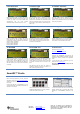
8. Set Network ID
Push the joystick down to display the screen
shown above. This lets you set the ID of the node
in case you need to run several PER tests
simultaneously and you have multiple
development kits. Leave this set to 1 for now.
9. Packet Length
Push the joystick down to display the screen
shown above. This lets you set the length of the
packets to be transmitted. The packet length will
affect the measured packet error rate. Push the
joystick left or right to select the packet length you
want to use.
10. Number of Packets
Push the joystick down to display the screen
shown above. This lets you set the number of
packets to be transmitted. Set this to the desired
value using the joystick.
11. Select RF Settings
Push the joystick down to display the screen
shown above. This lets you select preset RF
configurations, including modulation and data rate
Preset 0: 2-FSK, 2.4 kBaud
Preset 1: 2-FSK, 10 kBaud
Preset 2: MSK, 250 kBaud
Preset 3: MSK, 500 kBaud
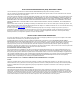
12. Select Mode
Push the joystick down to display the screen
shown above. Use the joystick to select master
mode. The EB you have configured now will be
the master in the PER test.
13. Configure 2
nd
EB
Perform steps 3 through 11 on the second EB.
Push the joystick down until you get the display
shown above. Leave this EB in slave mode.
14. Start PER
Push the joystick down on both EBs, and the
screen shown above is displayed. Push the
joystick right on the slave EB first, and then push
the joystick right on the master EB. The PER test
will start when the two nodes have successfully
connected.
15. Run PER Test
The uppermost line of the LCD will show the PER
for packets transmitted from the slave to the
master, while the second line will show the PER
for packets transmitted from the master to the
slave.
The PER test will end when the number of
packets you selected in step 10 is reached or if
100 consecutive packets are lost.
16. References
Please visit www.ti.com and
http://www.ti.com/tool/cc2500emk
Download the CC2500DK User Manual, the
SmartRF™ Studio software, examples, as well as
datasheets, reference designs and application
notes.
You will also find a lot of information on the TI
E2E forum at http://e2e.ti.com
We hope that you will enjoy working with the
CC2500 device.
SmartRF™ Studio
1. Download and Install
Before connecting the EB to your PC, download
SmartRF™ Studio from www.ti.com/smartrfstudio.
Install the program and follow the instructions in
the wizard.
Connect the EB with a CC2500EM to the PC
using the USB cable and install the USB driver as
described in the manual.
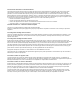
2. Launch SmartRF Studio
Launch SmartRF Studio and double click on the
highlighted CC2500 device icon to get complete
control of the device from the PC.
3. Configure the Radio
You can now configure the radio, run tests, export
register settings and run link tests with another
CC2500 on a SmartRF04EB connected to the
PC.