CC2531 NANO USB stick User’s Guide
Table of Contents 1 2 3 4 4.1 4.2 4.3 4.4 4.5 INTRODUCTION ...................................................................................................................... 4 ACRONYMS AND ABBREVIATIONS ................................................................................... 5 HW REQUIREMENTS ............................................................................................................. 6 NANO USB STICK SERIAL BOOT LOADER ........................................................
Table of Figures Figure 1: NANO USB stick and standard USB stick .................................................................. 6 Table of Tables Table 1: NANO USB and standard USB pin assignements .......................................................
1 Introduction The NANO USB stick is a miniature USB interface for 2.4GHz wireless applications. The design is based on a CC2531 System-on-Chip with an IEEE 802.15.4 radio. The NANO USB stick supports ZigBee and RF4CE applications. Typical applications includes: ZigBee RF4CE USB HID(Human Interface Device) ZigBee RF4CE serial port interface ZigBee gateway and commisioning interface for PC The NANO USB stick simplifies development of USB interface for ZigBee and RF4CE applications.
2 Acronyms and Abbreviations LED Light Emitting Diode LPW Low Power Wireless MCU Micro Controller RF Radio Frequency RF4CE Radio Frequency for Consumer Electronic SoC System on Chip TI Texas Instruments USB Universal Serial Bus 5/21
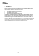
3 HW requirements Since the NANO USB stick has no I/O connections or LEDs for user interface it is recommended to use a standard CC2531 USB dongle for SW development and prototyping before loading the code onto the NANO USB stick. The NANO USB stick is compatible with regards to USB interface and radio interface to the standard CC2531 USB dongle.
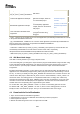
P1_6 I/O Pin header GND P1_7 I/O Pin header GND P2_0 Not connected GND P2_1 Debug data Debug data P2_2 Debug clock Debug clock P2_3 Not connected GND P2_4 Not connected GND Table 1: NANO USB and standard USB pin assignments The debug interface on the NANO USB stick is accessible on test points between the USB connector pins but these test points are small and difficult to access.
Linker_xxx.xcl Linker file usb_cdc_driver_cc2531_PID16B2.inf USB drivers usb_cdc_driver_cc2531_PID16A8.inf Z-stack ZNP Applications Example ZigBee Network Processor application example, based on the Z-stack ZNP project http://focus.ti.com/docs/t oolsw/folders/print/zstack.html RF4CE RNP Application Example ZigBee Remote Network Processor(RNP) application example, based on the RemoTI RNP project http://focus.ti.com/docs/t oolsw/folders/print/remo ti.
5. First Erase the flash by selecting Erase in Actions and then click Perform Actions 6. Then program the flash by selececting Erase and Program or Erase, program and verify, then click Perform actions. 4.4 SBL Compatible Application Code Image In this section you will be guided through the steps needed to convert an already existing Z-Stack 2.4.0 or RemoTI 1.2.1 application (in this case the RemoTI RNP application and, in parallel, the Zstack ZNP application) into one that is compatible with the SBL.
a. For the Z-stack: Add the following line to the "Post-build command line": "$PROJ_DIR$\tools\znp.bat" "$PROJ_DIR$\tools" "CC2531-ProdSBL" b. For the RemoTI stack:Add the following line to the "Post-build command line": "$PROJ_DIR$\pp_cc2531f256sb.bat" "$PROJ_DIR$" 8. Now select "Linker" category in the left panel a.
b.1) For the RemoTI stack : in the Output tab, in the Fornat Section, select Debug information for C-SPY, and check "With runtime control modules" and "Allow C-SPY - specific extra ouput file" b.
9. For the Z-stack-based ZNP project only: a. Select "C/C++ Compiler" category in left panel b. Select "Preprocessor" tab in right panel c.
4.5.1 Note on the batch files: znp.bat and pp_cc2531f256sb.bat use tools located in different directories, therefore be careful to respect the proper location of your files: znp.bat : calls znp.js which shall be located in "$PROJ_DIR$\tools" (1st option of znp.bat) where $PROJ_DIR$ refers to your project directory containing znp.eww. znp.js usessim2bin.exe wich actually converts a .sim file into a .bin file. The .sim file is an output of IAR, sim2bin.
4.6 Download a New Application Image via SBL Once an SBL compatible binary file has been generated, you can download it on the NANO USB stick using the SBDemo tool. 4.6.1 Serially boot the new Application Image (binary file): 1. Connect the NANO USB stick into a USB port 2. Open SBDemo.exe 3. Click on the “...” button and browse to your application image, ex: a. For the Z-stack: “Projects\zstack\ZNP\CC253x\dev\ CC2531ZNP-Prod.bin” b. For the RemoTI stack: “Projects\RemoTI\RNP\CC2530EB\CC2531F256_SB\Exe\
4.6.2 Remark about the Application The NANO USB stick dongle has almost* all of its pins connected to ground; therefore you should set these pins to be input pull-down at the beginning of your application to reduce current consumption. After a reset the default state is input pullup for all GPIOs. * Port0, Port1 and I/O 2.0, 2,3, 2.4 4.7 4.7.
Texas Instruments (TI) provides the enclosed Evaluation Board/Kit/Module (EVM) under the following conditions: The user assumes all responsibility and liability for proper and safe handling of the goods. Further, the user indemnifies TI from all claims arising from the handling or use of the goods. Should this evaluation board/kit not meet the specifications indicated in the User’s Guide, the board/ kit may be returned within 30 days from the date of delivery for a full refund.
For EVMs annotated as FCC – FEDERAL COMMUNICATIONS COMMISSION Part 15 Compliant Caution This device complies with part 15 of the FCC Rules. Operation is subject to the following two conditions: (1) This device may not cause harmful interference, and (2) this device must accept any interference received, including interference that may cause undesired operation. Changes or modifications not expressly approved by the party responsible for compliance could void the user's authority to operate the equipment.
For EVMs annotated as IC – INDUSTRY CANADA Compliant This Class A or B digital apparatus complies with Canadian ICES-003. Changes or modifications not expressly approved by the party responsible for compliance could void the user’s authority to operate the equipment. Concerning EVMs including radio transmitters This device complies with Industry Canada licence-exempt RSS standard(s).
Important Notice for Users of this Product in Japan】 This development kit is NOT certified as Confirming to Technical Regulations of Radio Law of Japan! If you use this product in Japan, you are required by Radio Law of Japan to follow the instructions below with respect to this product: (1) Use this product in a shielded room or any other test facility as defined in the notification #173 issued by Ministry of Internal Affairs and Communications on March 28, 2006, based on Subsection 1.
EVALUATION BOARD/KIT/MODULE (EVM) WARNINGS, RESTRICTIONS AND DISCLAIMERS For Feasibility Evaluation Only, in Laboratory/Development Environments. Unless otherwise indicated, this EVM is not a finished electrical equipment and not intended for consumer use.
classified as FDA Class III or similar classification, then you must specifically notify TI of such intent and enter into a separate Assurance and Indemnity Agreement.