
User manual

Installation & Launch: (continued)
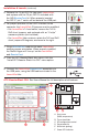
5. Remove the 14-pin DIP ICs from each LaunchPad,
and replace with the 20-pin DIP ICs included with
the AIR-BoosterPack kit. When properly inserted,
the DIP IC ‘pin 1’ notch will be towards the USB port.
6. For proper operation of the UART interface to the
computer, the LaunchPad J3 jumpers must be modifi ed:
– For LaunchPad v1.4 and earlier, remove the TxD &
RxD shunt jumpers, and replaced with an “X-style”
crossover pattern (not included).
– For LaunchPad later versions, rotate the TxD and RxD
shunt jumpers 90 degrees, as shown to the right.
7. Plug a BoosterPack module into each LaunchPad,
ensuring proper orientation. When properly installed,
the Rocket logos will ‘line-up’ on the LaunchPad
and BoosterPack.
8. From the ATC-BoosterStack disc menu, click the
“Install ATC-Booster Stack Lite GUI” menu option.
9. Connect the LaunchPad/BoosterPack assemblies to
the USB ports, using the USB cables included in the
LaunchPad kits.
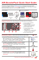
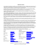
ATC-BoosterStack GUI: See Users Manual for full description of all features
v1.4 & earlier:
Later versions:
A Data traces
(RSSI, temperature)
B Trace show/hide
C RF confi guration control
D Paired node list
E S2 Switch (pairing)
F Green LED indicator
A
B
C
E F
D