
User manual


Installation & Launch: (continued)
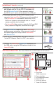
10. Launch the ATC – BoosterStack Lite software. The GUI
screen will appear, and a trace for hub-node temperature
will appear.
IMPORTANT NOTE: The BoosterPack is designed to comply with regulations in
the following regions:
Europe – ETSI (default)
North America – FCC / IC
If the intended location of use is not within these regions, then you must fi rst
check with local regulatory agencies to determine any permissions/license/etc.
are required prior to operation.
See Disclaimers and Regulatory Information included with the kit for
more information.
11a. For use in Europe, skip to step 12.
11b. For use in North America, follow these steps:
– Plug just one LaunchPad/BoosterPack USB cable into
the computer.
– Under “Logical Radio” select “1 A110LR09A, FCC”.
– Click “Apply Confi guration Changes”, the change is
stored in the fl ash memory.
– Repeat this step for the remaining LaunchPad/
BoosterPack units (plugging only one in at a time).
– Re-connect all LaunchPad/BoosterPack assemblies
to the computer.
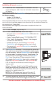
12. The BoosterPack fi rmware IC’s are shipped by default as
‘hub node’ (non-transmitting on startup) to satisfy regula-
tory requirements, and one BoosterPack must be toggled
to “sensor node” for pairing to occur. The following is a
subset of the full instructions contained in the Booster-
Pack Users Manual (see CD documentation folder).
a) To toggle the BoosterPack from hub to sensor node,
triple-click LaunchPad switch S2. The LaunchPad red
LED will blink 3x to indicate successful change to
‘sensor node’.
b) Press “Discover Nodes” on the GUI, and then imme-
diately press and hold the sensor node “S2” switch for
2 seconds. When paired correctly, the sensor node will
appear in the ‘paired nodes’ list.
NOTE: The GUI display may ‘gray out’ for up to 10
seconds while nodes are discovered, this is normal.
13. To identify a particular node, click the “Green LED” check
box on the paired nodes list to toggle the node LED.
Still not connected? See Users Manual for troubleshooting!
3X