
User's Guide Power Supply ADS5525, 27, 45, 46, 47,


www.ti.com
f
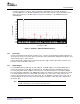
IN
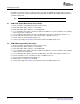
− Input Frequency − MHz
SNR − Signal-to-Noise Ratio − dBFS
G001
9.97 19.94 30.13 40.33 50.13 60.13 69.59 79.87 89.75 100.33 130.13 170.13
68
69
70
71
72
73
74
1 Decoupling Cap
Baseline-All Decoupling Caps
3.2.3 Analog Inputs
Circuit Description
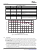
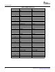
Table 2. EVM Power Options
BANANA JACK NAME VOLTAGE DESCRIPTION
J9 Device AGND GND
J10 AGND GND
J11 Device AVDD 3.3 Device analog supply
J12 Amplifier negative –5 THS4509 Vs– supply
rail
J13 Amplifier positive rail 5 THS4509 Vs+ supply
J14 Auxiliary power 5 Supplies power to all peripheral circuitry including the FPGA
and PROM. Voltages rails are created by using TI's TPS75003
voltage regulator.
J15 Device DVDD 3.3 Device internal digital output supply
J16 DGND GND
J17 DGND GND
J20 If TP11, TP12, and TP13 are tied low, the TPS75003 is
disabled. In this case, one can supply 3.3 V to pin 1, 1.2 V to
pin 2, and 2.2 V to pin 3 of J20 while connecting the ground to
J17.
Figure 1. ADS5547 SNR Performance vs Decoupling
The EVM can be configured to provide the ADC with either transformer-coupled or differential amplifier
inputs from a single-ended source. The inputs are provided via SMA connector J3 for transformer-coupled
input or SMA connector J1 for differential amplifier input. To set up for one of these options, the EVM must
be configured as follows:
1. For a 1:1 transformer-coupled input to the ADC, a single-ended source is connected to J3. Confirm
that SJP4 has pins 2 and 3 shorted, and that SJP5 has pins 2 and 3 shorted. The transformer used,
the Mini-Circuits TC4-1W, forms an inherent band-pass filter with a pass band from 3 MHz to 800 MHz.
This is the default configuration for the EVM.
2. One can use a TI THS4509 amplifier to drive the ADC by applying an input to J1. Reconfigure SJP4
and SJP5 such that both have pins 1 and 2 shorted. A 5-VDC supply must be connected to the board
to provide power to U3 for this configuration.
The THS4509 amplifier path converts a single-ended signal presented on J1 into a differential signal.
8 SLWU028B – January 2006 – Revised November 2006
Submit Documentation Feedback