
Datasheet

LMH6612
0.1 PF
10 PF
0.1 PF
V
+
1.24 k:
1 nF
150 pF
549:
V
+
-
+
22:
390 pF
14.3 k:
5.6 PF
14.3 k:
1 PF 549:
ADC121S705
0.1 PF
10 PF
V
+
LMH6612
0.1 PF
10 PF
0.1 PF
V
+
1.24 k:
1 nF
150 pF
549:
V
+
-
+
14.3 k:
5.6 PF
14.3 k:
1 PF 549:
22:
390 pF
+IN
-IN
LMH6611, LMH6612
www.ti.com
SNOSB00K –NOVEMBER 2007–REVISED OCTOBER 2013
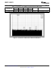
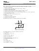
The performance of the LMH6612 with the ADC121S625 is shown in Table 2.
Table 2. Performance of the LMH6612 Combined with the ADC121S625
Amplifier SINAD SNR THD SFDR ENOB Notes
Output/ADC Input
(dB) (dB) (dB) (dBc)
2.5 68.8 69 −81.5 75.1 11.2 ADC121S625 @ f = 20 kHz
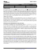
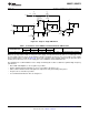
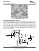
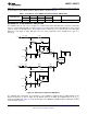
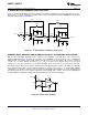
DIFFERENTIAL TO DIFFERENTIAL ADC DRIVER
The LMH6612 dual op amp can be configured as a differential to differential ADC driver to buffer a differential
source to a differential input ADC as shown in Figure 72. The differential to differential ADC driver can be formed
using two single to single ADC drivers. Each output from these drivers goes to a separate input of the differential
ADC. Here, each single to single ADC driver uses the same components and is configured for a gain of -1
(inverting).
Figure 72. Differential to Differential ADC Driver
The following table summarizes the performance of the LMH6612 combined with the ADC121S625 at two
different frequencies. In order to utilize the full dynamic range of the ADC, the maximum input of 2.5 V
PP
is
applied to the ADC input. Figure 73 shows the FFT plot of the LMH6612 and ADC121S625 combination tested at
f = 20 kHz input frequency.
Copyright © 2007–2013, Texas Instruments Incorporated Submit Documentation Feedback 27
Product Folder Links: LMH6611 LMH6612