Maintenance Manual ExtensaTM 660 Series Notebook Computers 9813214-0001, Rev.
Copyright © 1996, 1997 Texas Instruments All Rights Reserved ExtensaTM 660 Series Notebook Computers Maintenance Manual TI Part No. 9813214-0001, Rev. A Original Issue: December 1996 Revision A: February 1997 Changes may be made periodically to the information in this publication. Such changes will be incorporated in new editions of this manual.
Preface Introduction This manual provides installation, operation and servicing data for the ExtensaTM 660 Series Notebook Computers. Intended Audience This manual is primarily intended for use by qualified service technicians but contains information useful to non-technical users.
Other Manuals About the System The following documents provide additional information related to the Extensa Notebook Computer Series: ♦ Extensa Series Notebook Computers Users Guide - Contains user reference information for the Extensa 660 Series Notebook Computers.
Contents Paragraph Preface Introduction - - - - - - - - - - - - - Intended Audience - - - - - - - - - Contents- - - - - - - - - - - - - - - - Other Manuals About the System Ordering Parts and Supplies - - - Page - - - - - - - - - - - - - - - - - - - - - - - - - - - - - - - - - - - - - - - vii - vii - vii -viii -viii Introduction - - - - - - - - - - - - - - - - - - Product Overview - - - - - - - - - - - - - - - Extensa 660 Series Notebook Features Video Display Feature
Contents (continued) Paragraph Section 2 Installation (continued) Page Installing External Notebook Options - - - - - - - - - - - - - Installing Ext.
Contents (continued) Paragraph Section 4 Theory of Operation Page Introduction - - - - - - - - - - - - - - - - - - - - - - - - - Notebook Functional Overview - - - - - - - - - - - - - System Processor - - - - - - - - - - - - - - - - - Memory Subsystem - - - - - - - - - - - - - - - Main Memoy- - - - - - - - - - - - - - - - Flash ROM - - - - - - - - - - - - - - - - - System Controller Function- - - - - - Video Subsystem - - - - - - - - - - - - - - - - - Sound Subsystem- - - - - - - - - - - - - - - - - Key
Contents (continued) Paragraph Section 6 Field Service (continued) Required Tools and Equipment - - - - - - - - - - - - - - - - - - - - - - - - - - Notebook FRUs - - - - - - - - - - - - - - - - - - - - - - - - - - - - - - - - - - - - Cover-Display Assembly - - - - - - - - - - - - - - - - - - - - - - - - - - System Base Assembly - - - - - - - - - - - - - - - - - - - - - - - - - - - FRU Removal/Replacement Procedures - - - - - - - - - - - - - - - - - - - - Removing/Replacing the Primary Battery Pack - - - -
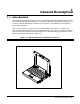
1 General Description 1.1 Introduction This manual contains field and factory level servicing information for the ExtensaTM 660 Series Notebook Computers (Figure 1-1) marketed by Texas Instruments. The first six sections contain information common to all members of the Extensa 660 Family of Notebook Computers. This section provides a general overview of the Extensa 660 Series, describes the standard and optional features, and identifies the major assemblies and subassemblies.
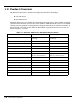
1.2 Product Overview The Extensa 660 Series contains two major product lines including: ♦ 660 CD Series ♦ 660 CDT Series Both notebook series are similar in construction and appearance, have similar operating controls and indicators and use the same software. Both notebook series use a similar startup self test program and diagnostics program (described in detail in Section 5 of this manual). The two models differ in Hard Drive capacity and LCD screen size as listed in Table 1-1 below.
1.3 Extensa 660 Series Notebook Features The Extensa 660 Series Notebook Computers are large screen, high-performance, multimedia notebooks powered by the Intel® P54CSLM Pentium® Processor Chip (133-MHz).
- Provisions for installation of second rechargeable battery pack in the Media Bay for extended portable operation. - Li-Ion primary battery option ♦ Powerful expansion capabilities including: - Advanced PCI Card slot (accessible from door at base of notebook), 120-pin port (PCI Bus plus sidebands).
Internal Microphone Notebook Release latch Left Speaker LCD Built-in Keyboard Right Speaker Select Buttons Media Bay Device (CD-ROM, FDD or second Battery) (Release Latch Underneath) Glidepad (mouse) Primary NiMH Battery Pack Media Bay Release Latch Left Side of Notebook APCI Compartment Expansion Memory Compartment AC Adapter Connector Power Button Battery Release Latch (Primary Battery) APCI Access Cover Kensington Lock Slot PCMCIA Card Slots Hard Disk Drive Bottom of Notebook HDD Module Fig
1.3.1.1 Internal LCD The Extensa 660 Series Notebooks contain one of the following LCDs (model dependent): ♦ 12.1-inch DSTN display (660CD Only) ♦ 11.3-inch TFT 1.3.1.2 External CRTs The Extensa 660 Series Notebooks are equipped with a 15-pin SVGA connector that can drive an external CRT (either alone or simultaneously with the internal LCD). When the notebook is set to the SimulSCAN mode, a minimum resolution of 800 x 600 x 256 colors is supported.
1.3.2 Keyboard Features The Extensa 660 Series Notebooks contain a built-in 86/87-key keyboard (Figure 1-3) compatible with the IBM® enhanced 101/102-key keyboard. The keyboard contains 12 programmable function keys, an embedded numeric keypad (Figure 1-4) and dedicated control keys (hot keys).
1.3.3 Software Features As a standard feature, the Extensa 660 notebooks are factory loaded with dual load (Windows® 95 or Windows for Workgroups) software to allow the user to configure the notebook’s operating system environment as summarized in Table 1-2.
1.3.4 Standard Peripheral Devices As standard features, the Extensa notebooks include an internal IDE hard drive, a 3.5-inch floppy disk drive, a CD-ROM drive and built-in glidepad (mouse device). 1.3.5 660 Series Connectivity Features As standard features, the Extensa 660 Series notebooks includes most standard desktop ports including a serial port, parallel port, PS/2 port, and external VGA port.
Table 1-3 660 Series External Ports Port Assignment Description External VGA Port 15-pin Female connector used to attach an external SVGA monitor to the notebook. Serial Port 9-pin Male connector used to attach an RS-232 serial device to the notebook. Parallel Port 25-pin Female connector used to attach a bidirectional printer or an external floppy disk drive (requires special cable for use with floppy disk drive).
1.3.7 Advanced PCI Card Options The Extensa 660 Series Notebooks contain provisions for an advanced PCI Card (installs from the bottom of the notebook by removing the APCI Cover as shown in Figure 1-6). Advanced PCI Compartment Advanced PCI Connector Compartment with cover removed Bottom of Notebook Figure 1-6 Installing Advanced PCI Card 1.3.8 PCMCIA Card Options The Notebook contains an onboard PCMCIA Controller and two 64-pin sockets that can accept up to two credit-card size (14.
1.4 Notebook Batteries The notebook computer can use one of three types of batteries: ♦ Primary Battery - Nickel-Metal-Hydride type ♦ Primary Battery - Lithium-Ion type (option) ♦ Secondary Battery - Lithium-Ion type (option) The primary battery is housed in the battery compartment and the Secondary battery fits in the Media Bay compartment. The characteristics of the available batteries are listed in Table 1-5.
Table 1-6 shows how to interpret the battery indicators. Table 1-6 Interpreting the Battery Charge Indicators No. of Indicators On Charge in Battery None Less then 20% (ORG) 1 20% to 40% (GRN) 2 40% to 60% (GRN) 3 60% to 80% (GRN) 4 80% to 100% (GRN) 1.4.2 External Battery Charger Option An optional external battery charger is available that charges a battery outside of the computer (all three types of batteries used by the Extensa 660 Series).
PC-Doctor is typically user-friendly but if you don't understand a feature, contextsensitive help information is available at any time by pressing the F1 function key; pressing the F1 function key twice accesses the online Technical Reference Manual for PC-Doctor.
1.6 Extensa 660 Series Specifications General specifications for the Extensa 660 Series Notebooks are provided in Table 1-6. Table 1-6 Extensa 660 Specifications Characteristic CPU Model 660CD Model 660CDT Pentium P55CLM, 166 MHz; 3.1 Volt Pentium P55CLM, 166 MHz; 3.1 Volt Standard Module Standard Module Disk Storage Capacity: 1.4 GB 2.
Table 1-6 Extensa 660 Specifications Characteristic Built-in Mouse Device Model 660CD Model 660CDT Glidepad built-in to the base of the keyboard (select buttons just below Glidepad) Glidepad built-in to the base of the keyboard (select buttons just below Glidepadpad) LCD Aspect Ratio 1-1 1-1 Emulations: SVGA SVGA Video Memory Size 1.5 MB 1.
Table 1-6 Extensa 660 Specifications Characteristic RS-232-D Serial Port: Model 660CD Model 660CDT 9-Pin, male, sub-D-type connector 9-Pin, male, sub-D-type connector Method: EIA RS-232-D EIA RS-232-D Type: Asynchronous transmission Asynchronous transmission 110, 200, 300, 600, 1200, 2400, 4800, 9600, 19200 110, 200, 300, 600, 1200, 2400, 4800, 9600, 19200 Parity: Transmit: Odd, even, mark, space Odd, even, mark, space Receive: Data check: odd, even Data check: odd, even Line control:
1.
2 Installation 2.1 Introduction This section contains unpacking and preparation for use instructions for the Extensa 660 Series Notebook Computers.
2.3 Installing Internal Notebook Options If you have no internal options to install at this time, skip to Paragraph 2.4. Otherwise, continue with Paragraph 2.3.1. 2.3.1 Installing Main Memory Expansion (Optional) Main memory on the 660 Series Notebooks can be expanded using an EDO Small Outline Dual Inline Memory Module (EDO soDIMM).
Memory Expansion Compartment With Cover Removed soDIMM Socket Installing soDIMM in Socket Figure 2-1 Memory Expansion Removal/Replacement Note: After installing expansion memory in your notebook, you must run the PHDISK utility in order for the Save-To-Disk or 0V Suspend functions to operate correctly. 2.3.
In Windows 95 Follow these steps if your computer is running Windows 95. 1. From the Taskbar, select Start then Shut Down. 2. Select the Restart the Computer in MS-DOS mode. 3. Click on Yes. 4. Type PHDISK /C /F at the DOS prompt and press Enter. 5. The DOS screen appears and shows the save file name and size. Press any key to reset the system. The computer will reboot. In Windows for Workgroups Follow these steps if your computer is running MS-DOS and Windows for Workgroups. 1.
7. Replace the Advanced PCI Access Cover and all components removed in Steps 1 and 2 above. Refer to the User Documentation for the Advanced PCI option for further instructions. Advanced PCI Compartment Advanced PCI Connector Compartment with cover removed Bottom of Notebook Figure 2-2 Installing an Advanced PCI Card Option 2.3.4 Installing PCMCIA Options The Notebook has two connector slots for PCMCIA option cards.
PC Card Release Levers Figure 2-3 Installing PCMCIA Option Cards Note: When installing a Zoomed Video option card, the card must be installed in the upper card slot (slot 0 or A). Other option cards can be installed in either card slot.
2.4 Installing External Notebook Options 2.4.1 Installing Ext. Keyboard/Mouse/Numeric Keypad A PS/2 compatible Keyboard, mouse or an optional PS/2-compatible numeric keypad may be installed on the notebook via the mouse connector on the left rear port as shown in Figure 2-4. 6 4 2 Mouse/Keyboard Connector 5 3 Pin No.
2.4.2 Installing an External Parallel Printer The Notebook is equipped with an external, bidirectional, ECC/EPP compatible, 25-pin parallel printer port. The connector pinouts and connector location are shown in Figure 2-5.
2.4.3 Installing an External Serial Port Device The notebook contains an external RS-232 serial port with a 9-pin, male DB-9 connector as shown in Figure 2-6 (25-pin cables require the use of an adapter for use with the 9-pin port).
2.4.4 Installing an External VGA Monitor The notebook contains an external CRT port that can drive one of a variety of monitor resolutions and colors as summarized in Table 1-9. The associated connector location and pinouts are shown in Figure 2-7.
2.5 Battery Pack Installation 1. Turn off the computer and disconnect the AC adapter if attached to the computer. NOTE: If removing an existing battery, press the battery release latch located underneath the notebook as shown in Figure 2-8 and remove the battery. 2. Look for the hand hold and insert the battery with hand hold down until battery pack snaps in place.
2.6 Installing the AC Power Adapter Use the following procedures to connect the AC adapter to the system: Caution: Use only the AC adapter supplied with the computer; other adapters can damage the unit. 1. Remove the AC adapter from the packaging. Connect the round coaxial connector supplied with the notebook to the DC IN power receptacle on the left rear of the notebook as shown in Figure 2-9. 2.
process can cause irreversible file damage. Before starting the initial software load process, ensure that you have the following: ♦ Extensa 660 User’s Guide - Contains latest software installation instructions. ♦ AC Adapter/Access to AC power - Although the battery pack may have some charge, it may be insufficient for the entire set up. Loss of power during setup can cause irreversible file damage.
2.8 Backing Up System Files After setting up the operating system, the computer gives you the opportunity to back up the operating system on floppy disks. You can make your backups immediately following setup or later. When you choose to back up your operating system on floppy disks, you will need approximately 40 floppy disks for Windows 95 or 20 floppy disks for DOS+WFW. 2.9 Demo Program ♦ After completing setup, you can run a multimedia demo program.
Windows 95 1. Double-click on the Uninstall Demo icon on the desktop. 2. When the Uninstall window appears, you can choose a complete or partial uninstall. If you want to keep some parts of the demo, you can deselect those parts, then click on OK. Windows for Workgroups 1. In the Program Manager double-click on the Texas Instruments Multimedia group. 2. Double-click on the Uninstall Demo icon. 3. When the Uninstall window appears, you can choose a complete or partial uninstall.
3 Operating Instructions 3.1 Introduction This section contains a summary of notebook operating procedures useful for maintenance operations. For additional detail, refer to the Extensa Series Notebook Computer User’s Guide supplied with the notebook. 3.2 Controls/Indicators The operating controls and indicators for the 660 Series Notebooks are shown in Figure 3-1 and briefly described in the following paragraphs.
3.2.1 Power On/Off Switch The notebook contains an alternate action power switch located on the left side of the notebook as shown in Figure 3-1. The first time you press the power switch, power is turned on to the notebook. The next time you press the power switch, power is turned off. 3.2.
Table 3-1 LED Icon Descriptions Icon A Description Num Lock Indicator Lights when the embedded numeric keypad is toggled ON using the Num Lock hot key (Fn+F7). Refer to Using the Internal Numeric Keypad section for further details. Suspend Mode Indicator Lights when the computer is in Suspend mode. Flashes when the computer is in the 5V Suspend mode.
Table 3-2 Summary of Notebook Hot Key Sequences Function Key Sequence Toggle speaker output on/off Fn+End Stop a command or application Ctrl+Pause Resume a command or application Press any key Send the contents of the screen to the printer Shift+PrtSc Sets the notebook to echo keystrokes to the printer; prints a line when you press Enter; continues until you press Ctrl+P Ctrl+P Enable/disable the internal keypad Fn+T Warm boot Ctrl+Alt+Del Start Windows logo key Display the application’s c
Refer to your Windows 95 manual for more information on these Windows 95-specific keys and their functions. 3.2.4.2 DOS Special Keys Table 3-5 contains a list of the DOS special keys. Table 3-5 DOS Special Keys Hot Key Function Ctrl+Pause Stops a command or application; primarily used to stop the screen from scrolling; pressing any other key resumes the execution of the command or application.
4. Select the glidepad tab to customize the glidepad to your preference. 5. Click on Help for the Synaptics Glidepad drivers online documentation. 3.4 Using a CD-ROM Drive An optional CD-ROM drive installed in the modular bay of the computer provides fast access to text, programs, graphics, sound, animation and video on a standard CD. (With an optional MPEG PC Card installed, you can play back approximately 75 minutes of MPEG1-compressed, full-motion video from a CD.) 3.4.
3.5.1 Adjusting the Volume To adjust volume on your computer, press the following keys: ♦ Fn+PgUp: Increases speaker volume ♦ Fn+PgDn: Decreases speaker volume ♦ Fn+End: Turns mute On/Off 3.5.2 Sound Software The computer has pre-installed sound support utilities in the AudioRack32 group. These include: ♦ AudioRack™32 ♦ Audio Recorder 3.5.3 External Sound Equipment You can improve the quality of sound production and increase convenience by connecting external sound equipment.
3.6.1 Using the Fast Infrared (FIR) Port The FIR port, located on the rear of the computer, offers wireless communication with other Texas Instruments notebook computers or a variety of IRDA-compliant devices. Without a physical connection, you can print remotely, transfer files between computers, use a remote mouse during a presentation or receive information from a PDA or pocket organizer.
3.7.1 Lowering Inactivity Timeouts Inactivity timeouts turn off devices in the computer when you are not using them. Lowering the inactivity timeouts shortens the period of time the computer waits before turning off the device. 3.7.
3.7.4 Replacing the battery If you have a spare, charged battery, you can do one of the following. ♦ Insert a secondary battery into the modular bay. ♦ If you already have a battery in the modular bay, you can replace the primary battery without turning off the computer. ♦ If you cannot insert the spare battery into the modular bay, suspend operations to disk by pressing Fn+F2 and replace the battery. When you turn on the computer, the computer returns to the saved state. 3.7.
4 Theory of Operation 4.1 Introduction This section contains a general block diagram theory of operation description of the Extensa 660 Series Notebook Computers. Note: Various internal components may change on future models and busses/bus speeds are subject to change. 4.
FLASH BIOS 256KB PCMCIA OMEGA 82C094 CARD 1 GLIDE PAD CORE CHIP UMC UM8891BF-N, UM8892BF-N, UM8886BF-N Bank 1 8, 16MB (DIMM) CARD 0 KB CONTROLLER MITSUBISHI M38813M4 EXT. KB/MOUSE INTERNAL KB Pentium P55CLM166MHz COM1 PRINTER VGA CHIP C&T 65548 SUPER I/O NS PC87336VLJ VIDEO RAM 1MB HDD CD-ROM (8X, 10X) FDD LCM INVERTER CRT ON AC Input AC ADAPTER 66MHz 14.318MHz X'TAL CLOCK GEN ICS AV9154-43 +3.45V DC/DC CONVERTER +5V +12V 24MHz 14.
4.2.1 System Processor The System Processor function for the notebook is implemented on the System Board in the form of an Intel Pentium P55CLM 166 MHz Super scalar 586 Processor Chip. The processor operates in conjunction with RAM and ROM Memory and other control logic to process software instructions (BIOS, DOS, Windows, and applications). The processor communicates with the hard disk drive and the memory components using high speed busses.
Controller (206) into a single 208 QFP package. Major features of the System Logic Controller include: ♦ System: — Fully compatible with IBM PC/AT — Supports PCI Bus-Master mode — System Operation Voltage from 3V to 5.
— On Mode — Doze Mode — Sleep Mode — Suspend Mode — Auto Power Reduction Mode (APR) — Word Processing Mode (WP) — All Register Read/Writeable for 0V Suspend — Microsoft APM Compatible — Supports 0V Suspend — Demand Driven Clock Control — Supports Resume/Suspend Key — Auto Wake-Up Function — Three Low Battery Monitor Input — System Operating Voltage from 3V to 5.5V — Low Power Consumption (at 3.3V) — 50mA at Full On Mode — 25mA at Doze Mode — 100µA at SUSPEND Mode — 15µA at POWER-OFF Mode with RTC active 4.
external microphone and line inputs and headphone/speaker outputs. The sound subsystem also includes a variety of sound utilities that combine to provide additional multi-media functions: 4.2.6 Keyboard Subsystem The keyboard subsystem, implemented on the Keyboard Assembly and the System Board Assemblies Board, consists of the following major sections: ♦ Keyboard Assembly ♦ Keyboard Scanner ♦ Status LED Interface 4.2.
4.2.9 Power Subsystem The notebook is equipped with a software/hardware monitored/controlled Power Subsystem that minimizes battery usage for prolonged battery operation and automatically recharges the batteries when the notebook is used with an AC adapter. 4.2.9.1 AC Power Adapter The computer is equipped with a universal AC power adapter that converts AC voltage into DC voltage (approx. 46 Watts of power) used to operate the notebook and charge the batteries.
5 Troubleshooting Procedures 5.1 Introduction This section provides an overview of the fault isolation process, provides guidelines for isolating 660 Series computer malfunctions to replaceable subassemblies and provides instructions for executing diagnostics and interpreting error messages. 5.
START COMPUTER TROUBLE INDICATION ? NO PORT REPLICATOR PROBLEMS? YES When Power button is pressed, no indication of power is present (dark LCD, no Status icons lit, no disk drive activity, etc.) DEAD COMPUTER SYMPTOMS ? Yes YES NO Press Power button; Selftest automatically runs when power turned on. NO ATTACH DESKTOP DEVICES DIRECTLY TO NOTEBOOK TO ISOLATE PORT REPLICATOR PROBLEMS See Paragraphs 5.3.1 & 5.3.2 SEE PARAGRAPH 5.4 RUN SELF TEST ERROR MESSAGE ? YES SEE PARAGRAPHS 5.3.3.1 and 5.
5.3 Troubleshooting Procedures The built-in self test program and the disk resident diagnostics program (PC-Doctor) are useful tools in computer troubleshooting. However, if the computer has a power, keyboard or display problem, you must first solve this problem before running diagnostics. If the computer powers up and displays messages on the LCD or emits a series of beeps, skip to Paragraph 5.3.3 for further instructions. 5.3.
♦ Faulty LCD - Replace the cover-display assembly as described in Section 6 of this manual. ♦ Low battery - Use a fully charged battery and/or plug in the AC adapter. Table 5-1 contains fault isolation information for Display Problems on the notebook. Symptoms are listed along the left side of the chart and the various Display FRUs are listed along the top of the chart. Within the body of the table are the probabilities of each of the FRUs causing that particular problem.
5.3.3 Fault Isolation Using Power On Self Test When the computer is first powered up, it automatically performs a Power On Self Test (POST) that checks the notebook’s central hardware and memory functions. During POST (which lasts for a few seconds), the display shows copyright and version number information. Note: Some procedures in this paragraph require you to use keystroke sequences, such as Ctrl-Alt-Del. To execute a keystroke sequence such as this, you must press all three keys simultaneously. 5.3.
Table 5-2 Power On Self Test Error Messages Message Possible Cause Action Diskette drive A failure The drive failed or is missing. Check the drive to determine the problem. Diskette read failure press F1 to retry boot, F2 for SETUP utility The disk is either not formatted or is defective. Replace the disk with a bootable disk and retry. Display adapter failed, using alternate The primary video adapter failed. Check the primary video adapter.
Table 5-2 POST Error Messages (continued) Message Possible Cause Action No boot device available press F1 to retry boot, F2 for SETUP utility Either disk drive A:, the fixed disk, or both the disk and fixed disk are defective. Try rebooting. If problem persists, replace the disk or the fixed disk. No boot sector on fixed disk - press F1 to retry boot, F2 for SETUP utility The C: drive is not formatted or is not bootable. Format the C: drive and make it bootable.
Table 5-2 POST Error Messages (continued) Message Possible Cause Action Keyboard clock line failure The keyboard, the keyboard cable connection, or the keyboard controller is defective. Make sure the keyboard cable and keyboard are connected properly. Check the keyboard controller and the system board. Turn the power off, then back on again. If the problem persists, contact qualified service personnel. Keyboard data line failure The keyboard controller firmware has failed.
Try running PC-Doctor (Paragraph 5.5) if possible to verify the source of problem.
Table 5-3 Self Test Beep Messages Beep Code Port 80h Description 3-1-2 21h Master DMA Register Failure 3-1-3 22h Master Interrupt Mask Register Failure 3-1-4 23h Slave Interrupt Mask Register Failure None 25h Interrupt Vector Loading In Progress 3-2-4 27h Keyboard Controller Test Failure None 28h CMOS Power Failure and Checksum in Progress None 29h CMOS Configuration Validation in Progress 3-3-4 2Bh Screen Memory Test Failure 3-4-1 2Ch Screen Initialization Failure 3-4-2 2Dh
5.3.4 Run Time Error Messages In the event of a hardware/software error that occurs after completion of POST, the error messages listed and described in Table 5-4 may occur. Table 5-4 Run Time Error Message Troubleshooting Message Cause Action I/O card parity interrupt at address. Type (S)hut off NMI, (R)eboot, other keys to continue Memory on a peripheral card has failed. Check the memory cards installed in the system. Memory parity interrupt at address.
5.4 General Fault Isolation Procedures Table 5-5 contains a summary of general problems that may occur during operation of the notebook and the appropriate corrective actions that should be taken for each. For other symptoms, go on to Paragraph 5.5 and troubleshoot the notebook using PC-Doctor Diagnostics. In the event of problems using a Port Replicator, try attaching all desktop devices to the notebook to isolate the problem to either the notebook or the port replicator.
Table 5-5 General Troubleshooting Procedures (continued) LCD screen does not show data 1. Check the LCD Status Bar if Suspend mode is activated. Press any key or press the power button to resume operation and display. 2. Check if LCD cables are disconnected or loose. 3. Check if the display output is switched to the external monitor. 4. Check if the Contrast level is set to minimum. 5. Check if there is power. 6. Replace the LCD Inverter board found inside the LCD Panel. Battery Power does not last 1.
Table 5-5 General Troubleshooting Procedures (continued) M em o ry m a lfu n ctio n E x te rn a l k ey b o a rd o r P S / 2 m o u s e d o e s n ’t w o rk P C M C IA ca rd d o e s n o t w o rk M o u s e d o e s n ’t w o rk S e ria l d ev ice d o es n o t w o rk P a ra lle l d ev ice d o es n o t w o rk 5-14 Troubleshooting Procedures 1. C h e ck if th e m em o ry m o d u le is in s erted p ro p erly . 2. R ep la ce th e m e m o ry m o d u le . 3. R ep la ce th e m o th erb o a rd . 1.
5.5 Fault Isolation Using Diagnostics PC-Doctor, supplied with the Extensa Series Notebooks, is a powerful diagnostics tool that can help you determine the hardware configuration of a local or remote system, benchmark its performance, analyze the performance of all subsystems, and perform a suite of interactive and non-interactive tests on attached devices (such as printers, joystick devices, VGA monitors, SCSI devices, CD-ROM drives).
♦ Group of special purpose utilities to run other tests from PC-Doctor, perform a virus scan of the system, edit configuration files, surface scan hard drives, measure system performance, open a DOS prompt, provides terminal access to devices connected to serial ports, supports memory debug operations, enables remote operations, permits deep discharge of notebook batteries and provides an extensive test reporting function. 5.5.
5.5.4 Quitting PC-Doctor To exit PC-Doctor, select the Quit pull down menu and then select the Quit option. Note: For additional information, access the Online Reference Manual for PC-Doctor. 5.6 Board Level Troubleshooting Procedures Figures 5-2 through 5-19 contain board-level troubleshooting procedures for the Extensa 660 Notebook. Table 5-6 contains a diagram index to the troubleshooting procedures: Table 5-6 Troubleshooting Flowchart Index Figure No.
1 Vcc5=5V Vcc3=3.
2 Check MEMVCC=3.
3 Check CN4 and CRT Cable System Fails to Boot: CRT Interface Checks No Check L15, L21, L22, L23, L24 (Red, Green, Blue, Hsync, Vsync) No Check U20 (2093) Pin 71=33MHz, Pin 93=14,318MHz, Pin 82=32,768KHz Yes Check VGA Clock, 14,318MHz and 32,768KHz Yes END Figure 5-4 CRT Interface Troubleshooting Diagram 5-20 Troubleshooting Procedures
4 System Fails to Boot: FDD Interface Check BIOS Menu Setup O.K.
5 BIOS Setup O.K.
6 System fils to boot: Keyboard Interface Checks Keyboard FPC Cable O.K.
7 System Fails to Boot: CD-ROM Interface Checks Checked CD-ROM Power? Check U605(9956) Pin1 No VCC-CDROM=5V Yes Checked CD-ROM Data Bus? No Check U13 PIN 36, 37, 38, 39, 50, 51, 52, 53, 62, 63, 64, 65, 71, 72, 73, & 74 Yes Checked CD-ROM No Address Bus? Check U13 PIN68, PIN69, PIN70, HSA0, HSA1, HSA2 Yes Checked IRQ Signal? No Check U13 Pin86, DIRQ15 Yes END Figure 5-8 CD-ROM Interface Troubleshooting Diagram 5-24 Troubleshooting Procedures
8 System Fails to Boot: Glide Pad Interface Checks Check GLide Pad Data Signal No Check CN21 Pin2 GLPDATA Signal No Check CN21 Pin3 GLPCLK Signal Yes Check Glide Pad Power Yes Check Glide Pad Power No Check CN21 Pin1=5V No Check U8(38813) Pin14 IRQ12 Yes Check Glide Pad IRQ Yes END Figure 5-9 Glidepad Interface Troubleshooting Diagram Troubleshooting Procedures 5-25
9 System Fails to Boot: DC/DC Converter Interface Checks PRESS POWER SWITCH DC-IN = 20V BAT = 12V NO Check T3, F1, D12, D11, F2, Q5, D14 YES NO Check M/B SW2 = 5V Check SW1 YES NO 5V Check CN33 PIN4 for low pulse Check SW2 0V YES NO 5V U1, PIN 7 0V Check D29, D2, D3, U2, Q1, Q2, Q3, Q4, C14, R13, R14, D4, D5, R8, R9, R10, R11, R1 YES END Figure 5-10 DC/DC Converter Interface Troubleshooting Diagram 5-26 Troubleshooting Procedures
10 Plug-In AC Adapter System Fails to Boot: Battery Charger Interface Checks No Check F1, T3 DC_IN=19V Yes U4=5V No Check D18 Yes Charge Battery 1 or Charge Battery 2 No Check Charger Control Board (RBC3) U1, D8, D7 Check Battery Pack Yes Voltage & Temp END Figure 5-11 Battery Charger Interface Troubleshooting Diagram Troubleshooting Procedures 5-27
11 LED Indicator Function Troubleshooting Check Caps Lock LED No Check CN11 Pin4 CAP#=0V No Check CN11 Pin7 NUM#=0V No Check CN7 Pin 3 Yes Check NUM Lock LED Yes HDD Read/Write LED Yes Check CD-ROM, FDD, & LED No Check CN11 Pin2 CD/FDD/HDDLED#=OV, while any device access No Check Con11 Pin5 PMUEN#=0V, while power management (BIOS) enable No Check CN11 Pin6 SUS-LED#=5V~0V, 0V~5V Yes Check Power Management LED Yes Clock Suspend LED Blanking Yes Check Charge LED Check CN11 Pin8 CHarge=5V
12 System Boots: Serial Port Checks Check BIOS Setup No Enter Correct type for COM1 Yes Check Transmitting Signal Check U1(MAX213) No SOUT1 Yes Check Receiving Signal No Check U1(MAX213) SIN1 Yes Check MD(0~63) No Check U21(87338) Pin1, Pin100, IRQ3,IRQ4 Yes END Figure 5-13 Serial Port Function Troubleshooting Diagram Troubleshooting Procedures 5-29
13 Suspend Function Troubleshooting Check BIOS Power Management Setup No Enter Correct type Yes Suspend to RAM Suspend to Disk Yes Check Suspend Signal No Check U9 Pin 3 (SUSPEND#=0V) Check Suspend Signal Yes Check Resume Operation No Check U9 Pin 3 Susepend No Check U9 Pin 3 Suspend#=5V Yes No Check Resume Operation Check U9 Pin 3 Suspend#= 5V Yes Yes END Figure 5-14 Suspend Function Troubleshooting Diagram 5-30 Troubleshooting Procedures
System Boots: Cover Switch Function Checks 14 Check BIOS Setup Enter Correct Value No Yes Check Switch Press Cover Switch Check COVSW#=0V No Yes END Figure 5-15 Cover Switch Function Troubleshooting Diagram 15 System Boots: Cover Close Function Checks Cover Close Check YES Check COVSW#: Low when cover closed High when cover open NO Check D18, R112, C58 YES Check COVSW#: Normally High Low pulse when Cover Closes NO Check D18, R112, C58 YES END Figure 5-16 Cover Close Function Troubles
16 System Boots: External Keyboard Checks Check Keyboard Data No Check U8(38813) Pin17 EXT1DATA Signal No Check U8(38813) Pin16 EXT1CLK Yes Check Keyboard Clock Yes Check U8(38813) PIN15 IRQ1 Check IRQ Signal Yes END Figure 5-17 External Keyboard Function Troubleshooting Diagram 17 System Boots: PS/2 External Mouse Interface Check Check Mouse Data No Check U8(38813) Pin12 EXT2DATA No Check U8(38813) Pin13 EXT2CLK No Check U8(38813) PIN14 IRQ12 Yes Check Mouse Clock Yes Check IRQ S
System Boots: 1 8 Printer Port Interface Checks Check BIOS Setup No Enter Correct Type of Printer Yes Check the Data Bus No Check RP5, RP7 No Check RP2 Pin6(BUSY) Yes Check Busy Signal Yes Check U21(87338) Entire Circuit END Figure 5-19 Printer Port Interface Troubleshooting Diagram Troubleshooting Procedures 5-33
6 Field Service 6.1 Introduction This section contains general preventive and corrective maintenance procedures that apply to all members of the Extensa 660 Notebook family. The first part of the section describes the computer cleaning procedures and preferred handling procedures for sensitive components (e.g., disk drives, batteries).
♦ Never place anything on top of the computer, particularly when it is operating or charging (could result in overheating and damage to the computer). ♦ Never move the computer while the hard drive is rotating (press the Suspend button to put the computer in a Sleep mode before closing cover). ♦ Never expose the computer hard disk drive(s) or disks to strong magnetic fields such as those generated by transformers, speakers, or telephone handsets. 6.2.
6.3 Required Tools and Equipment All Extensa Notebook corrective maintenance procedures can be performed using the following tools: ♦ Tweezers ♦ Plastic Stick ♦ Small flat-blade screwdriver ♦ Small Phillips® screwdriver ♦ 5 mm Nut Driver Caution: All boards, options and peripherals contain components that are sensitive to static electricity. When handling any of these items, protect against static electricity by using wrist grounding straps and grounded working mats.
6.4.1 Cover-Display Assembly The Cover-Display Assembly shown in Figure 6-2, contains the LCD screen, DC-AC Inverter Board, DC-DC Inverter Board, bezel LCD cover and various other components as listed in Table 6-1.
Table 6-1 Cover Display Assembly FRU Listing FRU Description Assembly/ Disassembly Paragraph TI Part No. LCD Panel, 11.3", TFT (HO) 6.5.17 9813168-0001 LCD Panel, 11.3", TFT (LG) 6.5.17 9813169-0001 LCD Panel, 12.1", DSTN (SANYO) 6.5.17 9813170-0001 Display Back Cover, 11.3" (HO) 6.5.17 9813165-0001 Display Back Cover, 11.3" (LG) 6.5.17 9813207-0001 Display Back Cover, 12.1" (SANYO) 6.5.17 9813167-0001 11.3" Display Bezel 6.5.17 9813164-0001 12.1" Display Bezel 6.5.
Keyboard Assembly Heat Sink Assembly CPU PWB Top Cover Assembly CMOS Battery Glidepad Power Supply PWB Audio PWB Button PCMCIA PWB Door Battery/HDD Transfer PWB Main PWB Figure 6-3 System Base Assembly FRUs 6-6 Field Service Bottom Case Assembly
Table 6-2 System Base Assembly FRU Listing Base Assembly FRU Description Assembly/ Disassembly Paragraph TI Part No. PWB Assemblies Mainboard PWB Assembly, Extensa 66x 6.5.15 9813135-0001 CPU PWB Assembly 6.5.8 9813136-0001 Power Supply PWB Assembly 6.5.13 9813138-0001 HDD/Battery Transfer Board PWB Assembly 6.5.16 9813143-0001 Audio Board PWB Assembly 6.5.14 9813140-0001 LED Board PWB Assembly 6.5.11 9813142-0001 Glidepad Assembly w/Plastic 6.5.
Table 6-2 System Base Assembly FRU Listing Base Assembly FRU Description Assembly/ Disassembly Paragraph TI Part No. Nameplate, Logo Ref 9813173-0001 Nameplate, Model 660CD Ref 9813173-0002 Nameplate, Model 660CDT Ref 9813173-0003 PCMCIA Doors (w/Spring) Ref 9813175-0001 Cover Assembly, Advanced PCI Board 6.5.4 9813156-0001 Cover, Memory Expansion Section 2 9813178-0001 Right and Left Hinge Covers Ref 9813161-0001 HDD Cover Door 6.5.
Table 6-3 Customer-Replaceable Units (CRUs) Base Assembly FRU Description Assembly/ Disassembly Paragraph TI Part No. Options Battery, Primary, Li-Ion 6.5.1 9813130-0001 Battery, Secondary, Li-Ion 6.5.2 9813131-0001 External Battery Charger, U.S. Ref 9813134-0001 External Battery Charger, WW Ref 9813134-0004 Auto Adapter Ref 9813126-0001 Port Replicator, Extensa 65X/66X Ref 9813564-0001 FDD w/Cable, (External) 6.5.2 9813561-0001 HDD Kit, 2.1 GB 6.5.
Unplugging the Cable Connecting the Cable Figure 6-4 Removing/Installing Cables with ZIF Connectors 6.5.1 Removing/Replacing the Primary Battery Pack Before performing any of the assembly/disassembly procedures, always disconnect the AC adapter from the notebook and remove all battery packs. The procedure for removing and replacing the primary battery pack is as follows: 1. Turn off the computer and disconnect the AC adapter from the computer. 2.
Optional Media Bay Secondary Battery Pack (Li-Ion) NiMH or Li-Ion Primary Battery Secondary Battery Release Latch Primary Battery Release Latch Figure 6-5 Battery Removal/Replacement 6.5.2 Removing/Replacing a Media Bay Device The computer has a latch-controlled locking mechanism that prevents accidental removal of devices from the modular bay. Follow these steps to change modules. 1. Turn off the computer. 2. Press the release latch on the bottom of the computer as shown in Figure 6-6. 3.
Module Lock Grip Area Figure 6-6 Removing/Replacing a Media Bay Device 4. Unpack the new accessory. 5. Slide the new accessory into the modular bay and push the accessory until it latches into place. 6. Place the original accessory in a safe place. 7. Turn on the computer.
6.5.3 Removing/Replacing PCMCIA Options The procedure for removing and replacing the PCMCIA options is as follows: 1. Stop operation according to operating system (Windows 95 or Windows for Workgroups) instructions. 2. Press the upper card eject button to eject the upper card, lower button controls the lower card and use both buttons for Type III devices (refer to Figure 6-7). 3. To replace the PCMCIA device, remove any filler cards present and insert the device.
connectors and remove any installed PCMCIA options. 3. Turn the computer over and locate the APCI Access Cover as shown in Figure 6-8.
6.5.5 Removing/Replacing the Hard Disk Drive Assembly The procedure for removing and replacing the Hard Disk Drive assembly is as follows: 1. Power down the notebook, disconnect the AC adapter, if installed, and remove any installed battery packs as described in Paragraphs 6.5.1 and 6.5.2. 2. Disconnect any peripheral device interface cables from the external interface connectors. 3. Turn the computer over and remove the hard disk drive bay cover (refer to Figure 6-9). 4.
6.5.6 Removing/Replacing the Keyboard Assembly The procedure for removing and replacing the keyboard assembly is as follows: 1. Turn off the computer; disconnect the AC power adapter (if attached), and remove the battery packs as described in Paragraphs 6.5.1 and 6.5.2. 2. Press the Cover Release Latch and open the notebook to a full 180 degree position. 3. Locate the keyboard tabs along the top edge of the notebook.
6.5.7 Removing/Replacing the Heat Sink Assembly The procedure for removing and replacing the Heat Sink Assembly is as follows: 1. Turn off the computer; disconnect the AC power adapter (if attached), and remove the battery packs as described in Paragraphs 6.5.1 and 6.5.2. 2. Press the Cover Release Latch and open the notebook to a full 180 degree position. 3. Remove the Keyboard Assembly as described in Paragraph 6.5.6. 4.
6.5.8 Removing/Replacing the CPU PWB Assembly The procedure for removing and replacing the CPU PWB Assembly is as follows: 1. Turn off the computer; disconnect the AC power adapter (if attached), and remove the battery packs as described in Paragraphs 6.5.1 and 6.5.2. 2. Press the Cover Release Latch and open the notebook to a full 180 degree position. 3. Remove the Keyboard Assembly as described in Paragraph 6.5.6. 4. Remove the Heat Sink Assembly as described in Paragraph 6.5.7.
6.5.9 Removing/Replacing the Display Assembly The procedure for removing and replacing the Display Assembly is as follows: 1. Turn off the computer; disconnect the AC power adapter (if attached), and remove the battery packs as described in Paragraphs 6.5.1 and 6.5.2. 2. Press the Cover Release Latch and open the notebook to a full 180 degree position. 3. Remove four screws from the face of the LCD cover and pull the covers apart starting at the top of the Display (refer to Figure 6-13). 4.
6.5.10 Removing/Replacing the Top Cover Assembly The procedure for removing and replacing the Top Cover Assembly is as follows: 1. Turn off the computer; disconnect the AC power adapter (if attached), and remove the battery packs as described in Paragraphs 6.5.1 and 6.5.2. 2. Press the Cover Release Latch and open the notebook to a full 180 degree position. 3. Remove the Keyboard Assembly as described in Paragraph 6.5.6. 4. Remove the Heat Sink Assembly as described in Paragraph 6.5.7. 5.
6.5.11 Removing/Replacing the LED PWB Assembly The procedure for removing and replacing the LED PWB Assembly is as follows: 1. Turn off the computer; disconnect the AC power adapter (if attached), and remove the battery packs as described in Paragraphs 6.5.1 and 6.5.2. 2. Press the Cover Release Latch and open the notebook to a full 180 degree position. 3. Remove the Keyboard Assembly as described in Paragraph 6.5.6. 4. Remove the Heat Sink Assembly as described in Paragraph 6.5.7. 5.
6.5.12 Removing/Replacing the Glidepad Assembly The procedure for removing and replacing the Glidepad Assembly is as follows: 1. Turn off the computer; disconnect the AC power adapter (if attached), and remove the battery packs as described in Paragraphs 6.5.1 and 6.5.2. 2. Press the Cover Release Latch and open the notebook to a full 180 degree position. 3. Remove the Keyboard Assembly as described in Paragraph 6.5.6. 4. Remove the Heat Sink Assembly as described in Paragraph 6.5.7. 5.
6.5.13 Removing/Replacing the Power Supply PWB Assembly The procedure for removing and replacing the Power Supply PWB Assembly is as follows: 1. Turn off the computer; disconnect the AC power adapter (if attached), and remove the battery packs as described in Paragraphs 6.5.1 and 6.5.2. 2. Press the Cover Release Latch and open the notebook to a full 180 degree position. 3. Remove the Keyboard Assembly as described in Paragraph 6.5.6. 4. Remove the Heat Sink Assembly as described in Paragraph 6.5.7.
6.5.14 Removing/Replacing the Audio PWB Assembly The procedure for removing and replacing the Power Supply PWB Assembly is as follows: 1. Turn off the computer; disconnect the AC power adapter (if attached), and remove the battery packs as described in Paragraphs 6.5.1 and 6.5.2. 2. Press the Cover Release Latch and open the notebook to a full 180 degree position. 3. Remove the Keyboard Assembly as described in Paragraph 6.5.6. 4. Remove the Heat Sink Assembly as described in Paragraph 6.5.7. 5.
6.5.15 Removing/Replacing the Main PWB Assembly The procedure for removing and replacing the Power Supply PWB Assembly is as follows: 1. Turn off the computer; disconnect the AC power adapter (if attached), and remove the battery packs as described in Paragraphs 6.5.1 and 6.5.2. 2. Press the Cover Release Latch and open the notebook to a full 180 degree position. 3. Remove the Keyboard Assembly as described in Paragraph 6.5.6. 4. Remove the Heat Sink Assembly as described in Paragraph 6.5.7. 5.
6.5.16 Removing/Replacing the Battery/HDD Transfer PWB Assembly The procedure for removing and replacing the Battery/HDD Transfer PWB Assembly is as follows: 1. Turn off the computer; disconnect the AC power adapter (if attached), and remove the battery packs as described in Paragraphs 6.5.1 and 6.5.2. 2. Press the Cover Release Latch and open the notebook to a full 180 degree position. 3. Remove the Keyboard Assembly as described in Paragraph 6.5.6. 4.
6.5.17 Removing/Replacing the Display FRUs The procedure for removing and replacing the Display FRUs is as follows: 1. Turn off the computer; disconnect the AC power adapter (if attached), and remove the battery packs as described in Paragraphs 6.5.1 and 6.5.2. 2. Press the Cover Release Latch and open the notebook to a full 180 degree position. 3. Remove the Cover-Display Assembly as described in Paragraph 6.5.9. 4. Refer to Figure 6-21 and remove the desired display FRU. 5.
A Schematic Diagrams A.1 Introduction This section contains schematic diagrams for the Extensa 660 Notebook Computer.
Figure A-1 Motherboard PWB Logic Diagrams (Sheet 1 of 23) A-2 Schematic Diagrams
Figure A-2 Motherboard PWB Logic Diagrams (Sheet 2 of 23) Schematic Diagrams A-3
Figure A-1 Motherboard PWB Logic Diagrams (Sheet 3 of 23) A-4 Schematic Diagrams
Figure A-1 Motherboard PWB Logic Diagrams (Sheet 4 of 23) Schematic Diagrams A-5
Figure A-1 Motherboard PWB Logic Diagrams (Sheet 5 of 23) A-6 Schematic Diagrams
Figure A-1 Motherboard PWB Logic Diagrams (Sheet 6 of 23) Schematic Diagrams A-7
Figure A-1 Motherboard PWB Logic Diagrams (Sheet 7 of 23) A-8 Schematic Diagrams
Figure A-1 Motherboard PWB Logic Diagrams (Sheet 8 of 23) Schematic Diagrams A-9
Figure A-1 Motherboard PWB Logic Diagrams (Sheet 9 of 23) A-10 Schematic Diagrams
Figure A-1 Motherboard PWB Logic Diagrams (Sheet 10 of 23) Schematic Diagrams A-11
Figure A-1 Motherboard PWB Logic Diagrams (Sheet 11 of 23) A-12 Schematic Diagrams
Figure A-1 Motherboard PWB Logic Diagrams (Sheet 12 of 23) Schematic Diagrams A-13
Figure A-1 Motherboard PWB Logic Diagrams (Sheet 13 of 23) A-14 Schematic Diagrams
Figure A-1 Motherboard PWB Logic Diagrams (Sheet 14 of 23) Schematic Diagrams A-15
Figure A-1 Motherboard PWB Logic Diagrams (Sheet 15 of 23) A-16 Schematic Diagrams
Figure A-1 Motherboard PWB Logic Diagrams (Sheet 16 of 23) Schematic Diagrams A-17
Figure A-1 Motherboard PWB Logic Diagrams (Sheet 17 of 23) A-18 Schematic Diagrams
Figure A-1 Motherboard PWB Logic Diagrams (Sheet 18 of 23) Schematic Diagrams A-19
Figure A-1 Motherboard PWB Logic Diagrams (Sheet 19 of 23) A-20 Schematic Diagrams
Figure A-1 Motherboard PWB Logic Diagrams (Sheet 20 of 23) Schematic Diagrams A-21
Figure A-1 Motherboard PWB Logic Diagrams (Sheet 21 of 23) A-22 Schematic Diagrams
Figure A-1 Motherboard PWB Logic Diagrams (Sheet 22 of 23) Schematic Diagrams A-23
Figure A-1 Motherboard PWB Logic Diagrams (Sheet 23 of 23) A-24 Schematic Diagrams