
Datasheet
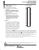


54AC16373, 74AC16373
16-BIT TRANSPARENT D-TYPE LATCHES
WITH 3-STATE OUTPUTS
SCAS121B – MARCH 1990 – REVISED APRIL 1996
5
POST OFFICE BOX 655303 • DALLAS, TEXAS 75265
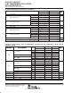
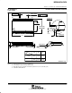
timing requirements over recommended operating free-air temperature range,
V
CC
= 3.3 V ± 0.3 V (unless otherwise noted) (see Figure 1)
T
A
= 25°C 54AC16373 74AC16373
UNIT
MIN MAX MIN MAX MIN MAX
UNIT
t
w
Pulse duration, LE high 5 5 5 ns
t
su
Setup time, data before LE↓ 1.5 1.5 1.5 ns
t
h
Hold time, data after LE↓ 3 3 3 ns
timing requirements over recommended operating free-air temperature range,
V
CC
= 5 V ± 0.5 V (unless otherwise noted) (see Figure 1)
T
A
= 25°C 54AC16373 74AC16373
UNIT
MIN MAX MIN MAX MIN MAX
UNIT
t
w
Pulse duration, LE high 4 4 4 ns
t
su
Setup time, data before LE↓ 1.5 1.5 1.5 ns
t
h
Hold time, data after LE↓ 2.5 2.5 2.5 ns
switching characteristics over recommended operating free-air temperature range,
V
CC
= 3.3 V ± 0.3 V (unless otherwise noted) (see Figure 1)
PARAMETER
FROM TO
T
A
= 25°C 54AC16373 74AC16373
UNIT
PARAMETER
(INPUT) (OUTPUT)
MIN TYP MAX MIN MAX MIN MAX
UNIT
t
PLH
D
Q
3.7 10.6 13.4 3.7 15.1 3.7 15.1
ns
t
PHL
D
Q
4.3 11.3 14 4.3 14.8 4.3 14.8
ns
t
PLH
LE
Q
4.6 12.9 15.8 4.6 18.6 4.6 18.6
ns
t
PHL
LE
Q
4.5 12.1 14.6 4.5 16.4 4.5 16.4
ns
t
PZH
OE
Q
4.2 11.8 14.8 4.2 17.5 4.2 17.5
ns
t
PZL
OE
Q
5.4 16.3 19.8 5.4 22.3 5.4 22.3
ns
t
PHZ
OE
Q
4.2 7.9 9.5 4.2 10.2 4.2 10.2
ns
t
PLZ
OE
Q
3.8 7.1 8.9 3.8 9.8 3.8 9.8
ns
switching characteristics over recommended operating free-air temperature range,
V
CC
= 5 V ± 0.5 V (unless otherwise noted) (see Figure 1)
PARAMETER
FROM TO
T
A
= 25°C 54AC16373 74AC16373
UNIT
PARAMETER
(INPUT) (OUTPUT)
MIN TYP MAX MIN MAX MIN MAX
UNIT
t
PLH
D
Q
3.1 6.7 8.5 3.1 9.7 3.1 9.7
ns
t
PHL
D
Q
3.5 7.3 9.1 3.5 10.1 3.5 10.1
ns
t
PLH
LE
Q
3.8 8.2 10.2 3.8 11.9 3.8 11.9
ns
t
PHL
LE
Q
3.6 7.8 9.7 3.6 10.9 3.6 10.9
ns
t
PZH
OE
Q
3.5 7.4 9.4 3.5 10.8 3.5 10.8
ns
t
PZL
OE
Q
4.3 9.1 11.3 4.3 12.8 4.3 12.8
ns
t
PHZ
OE
Q
3.9 6.6 8 3.9 8.8 3.9 8.8
ns
t
PLZ
OE
Q
3.7 5.9 7.4 3.7 8.1 3.7 8.1
ns
operating characteristics, V
CC
= 5 V, T
A
= 25°C
PARAMETER TEST CONDITIONS TYP UNIT
C
d
Power dissi
p
ation ca
p
acitance
p
er latch
Outputs enabled
C
L
=50
p
F
f=1MHz
43
p
F
C
pd
Po
w
er
dissipation
capacitance
per
latch
Outputs disabled
C
L
=
50
pF
,
f
=
1
MH
z
5
pF
PRODUCT PREVIEW information concerns products in the formative or
design phase of development. Characteristic data and other
specifications are design goals. Texas Instruments reserves the right to
change or discontinue these products without notice.