
Datasheet


54AC16373, 74AC16373
16-BIT TRANSPARENT D-TYPE LATCHES
WITH 3-STATE OUTPUTS
SCAS121B – MARCH 1990 – REVISED APRIL 1996
6
POST OFFICE BOX 655303 • DALLAS, TEXAS 75265
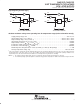
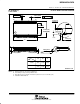
PARAMETER MEASUREMENT INFORMATION
50% V
CC
50%
50%
50%
V
CC
V
CC
0 V
0 V
t
h
t
su
VOLTAGE WAVEFORMS
Data Input
t
PLH
t
PHL
t
PHL
t
PLH
V
OH
V
OH
V
OL
V
OL
50% 50%
V
CC
0 V
50% V
CC
50% V
CC
Input
Out-of-Phase
Output
In-Phase
Output
Timing Input
(see Note B)
50% V
CC
VOLTAGE WAVEFORMS
From Output
Under Test
C
L
= 50 pF
(see Note A)
LOAD CIRCUIT
S1
2 × V
CC
500 Ω
500 Ω
Output
Control
(low-level
enabling)
Output
Waveform 1
S1 at 2 × V
CC
(see Note B)
Output
Waveform 2
S1 at GND
(see Note B)
V
OL
V
OH
t
PZL
t
PZH
t
PLZ
t
PHZ
50%
50%
V
CC
0 V
50% V
CC
20% V
CC
50% V
CC
80% V
CC
0 V
V
CC
GND
Open
VOLTAGE WAVEFORMS
t
PLH
/t
PHL
t
PLZ
/t
PZL
t
PHZ
/t
PZH
Open
2 × V
CC
GND
TEST S1
V
CC
0 V
50% 50%
t
w
VOLTAGE WAVEFORMS
Input
NOTES: A. C
L
includes probe and jig capacitance.
B. Waveform 1 is for an output with internal conditions such that the output is low except when disabled by the output control.
Waveform 2 is for an output with internal conditions such that the output is high except when disabled by the output control.
C. All input pulses are supplied by generators having the following characteristics: PRR ≤ 1 MHz, Z
O
= 50 Ω, t
r
= 3 ns, t
f
= 3 ns.
D. The outputs are measured one at a time with one input transition per measurement.
Figure 1. Load Circuit and Voltage Waveforms